Juno Development Board
Enablement
LAVA by default is configured to work with this DUT + LAA setup. If you opt for a different setup you’ll have to change your DUT + LAA device configuration on LAVA.
All Juno revisions (r0, r1 and r2) are supported by the single juno
device-type: the setup, recovery flow and health check are identical
across revisions. Record the board revision as device tags (for example
juno-r2 and r2) so that jobs targeting a specific revision can pin
it.
Components
The following components are required to fully automate the board:
Short RJ45 network cable
2.5/5.5mm barrel jack to MIB 2-pin connector, wired center positive
USB to serial adapter, with male DB9 connector
USB-A male to USB-B male cable
USB-A male to USB-C male cable (optional, see USB)
Juno Package
Some of the cables are inside the Juno package. The USB to serial adapter was not capable of sending data to the Juno, it is suggested to buy your own.
Hardware modification
No hardware modifications are required.
MIB
Configuration
No need to use any jumper on the Flylead MIB to set the voltage.
Recovery
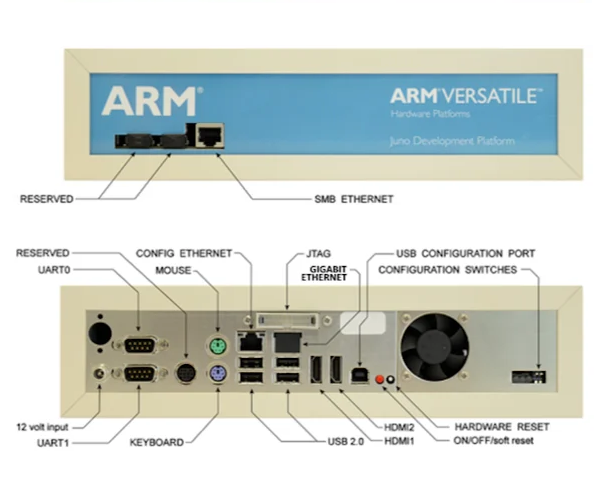
Connect the USB-A male to USB-B male cable to the LAA USB Port3 to the Juno
USB CONFIGURATION PORT.
Network
Connect the Juno front ethernet network interface called SMB ETHERNET to the
LAA private network interface.
Power
The Juno gets power from the 2.5/5.5mm barrel jack connected to the board and
the 12V header on the MIB.
Serial
Connect the USB to serial adapter cable from the carrier board port labeled
UART0 to the LAA USB Port2.
USB
This connection is optional: it’s only needed for jobs that boot an OS
from the LAA USB mass storage gadget (usbg-ms). Boards used purely for
firmware testing can skip it.
Connect the LAA USB OTG port (front facing) to any of the four Juno USB 2.0
ports. We usually make use of the top left port.