RB3gen2
Enablement
LAVA by default is configured to work with this DUT + LAA setup. If you opt for a different setup you’ll have to change your DUT + LAA device configuration on LAVA.
The RB3gen2 DUT can be automated using the RPi and 96 boards MIB.
Components
The following components are required to fully automate the board:
Short RJ45 network cable
USB-C male to USB-C male cable
USB-A male to MicroUSB male cable
For the OTG USB-C to MicroUSB connection:
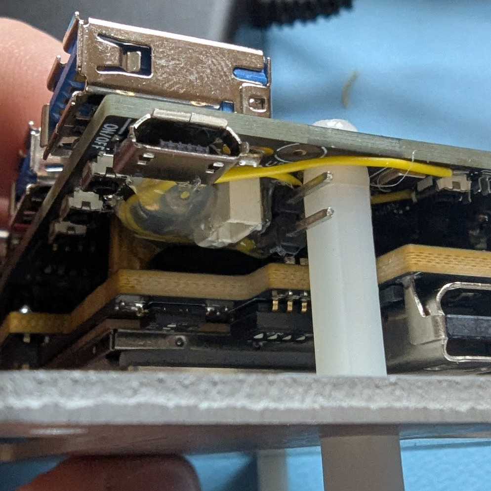
Hardware modification
In order to automate recovery, the DUT hardware should be modified.
Hardware modification
The DUT will not be automatizable without this modification.
DIP switches
Set the DIP switches as in the picture below.
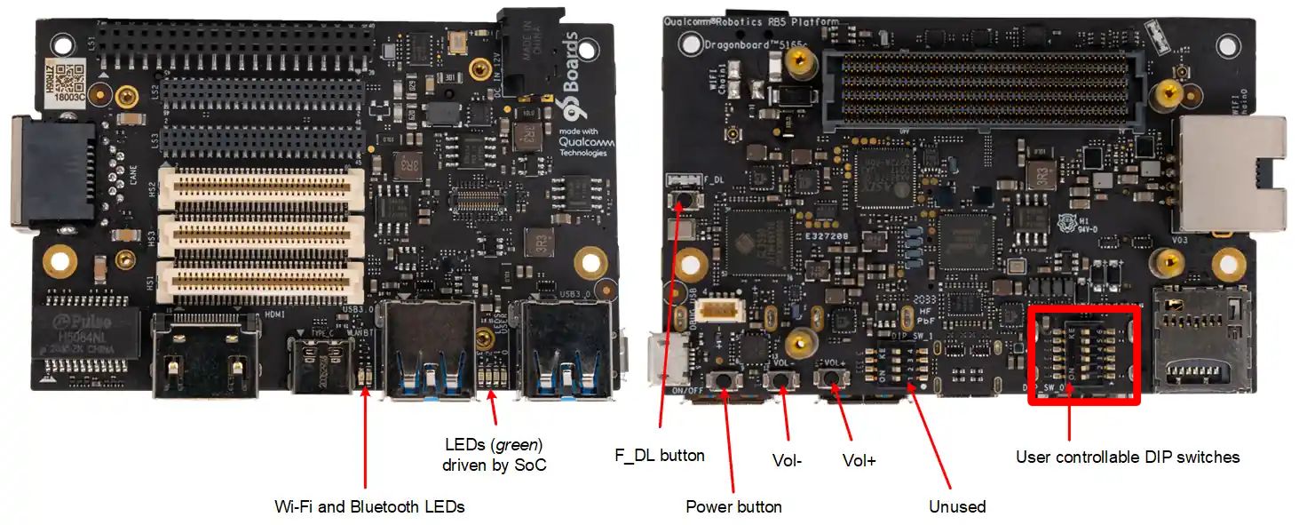
Buttons and DIP Switches
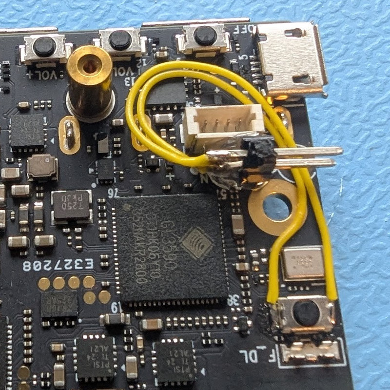
EDL button
A two-wires cable should be soldered around the F_DL button. This will be used to drive the value high or low to trigger recovery.
MIB
The following picture shows how to connect the RB3gen2 board to the MIB.
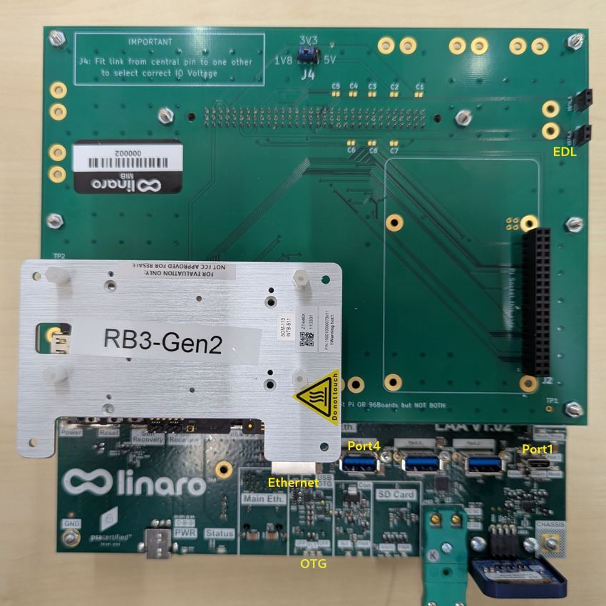
Connections
Configuration
Set the voltage level switch on the top of the MIB to 1v8.
Recovery
Connect the recovery wires cable to the RPi-96 MIB header labeled VBTN_A.
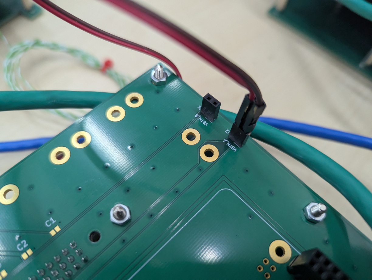
VBTN_A
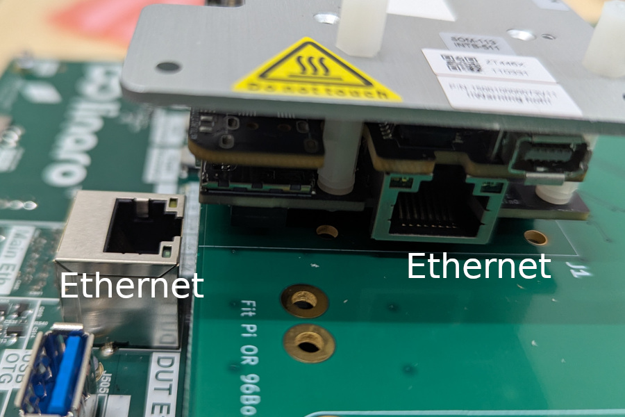
Network
Connect the RB3gen2 network interface to the LAA private network interface.
Power
The RB3gen2 gets power directly from the 96boards header interface.
Serial
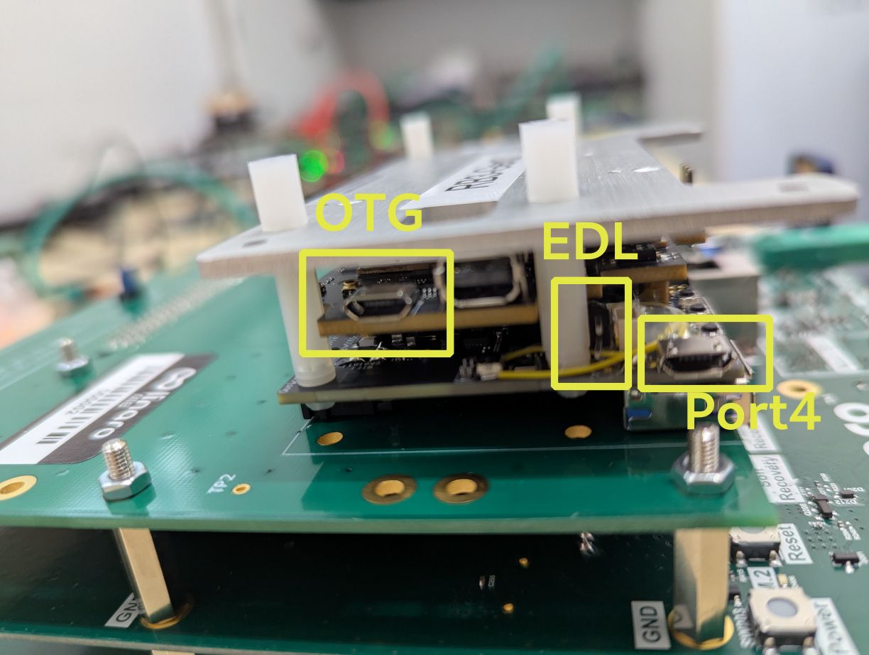
Connect a USB cable from the carrier board MicroUSB port to USB Port 4 on the SIB as shown above.
USB
Connect the LAA USB OTG port (front facing) to the RB3gen2 MicroUSB port shown in the picture above.
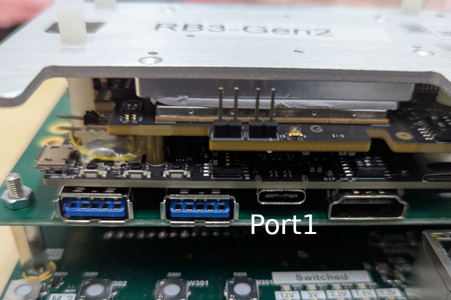
Flashing
Connect a USB-C cable from LAA Port 1 (facing upward) to the RB3gen2 USB-C port shown in the picture above.