Pixel 6 (gs101-oriole)
Enablement
LAVA by default is configured to work with this DUT + LAA setup. If you opt for a different setup you’ll have to change your DUT + LAA device configuration on LAVA.
WIP
The phone jig was assembled by trial and error and the current configuration may not be optimal. This guide should be considered a work in progress and may change in the future.
Pixel 6 LAA Fully Assembled
Components
The following components are required to fully automate the board:
3 x MG90D servos
USB Cereal
1x USB type C extension cable
2x USB type C male to type A male cable
Connections
USB Cereal
Currently the LAA only supports 115200 baud so the device needs to be configured for this rate:
adb reboot fastboot
fastboot oem uart enable
fastboot oem uart config 115200
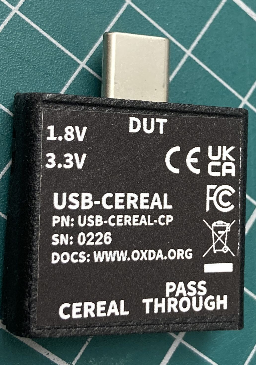
USB Cereal
The USB Cereal should be connected to DUT in the following way:
LAA |
Cereal |
DUT |
|---|---|---|
USB 4 |
Pass Through |
|
USB 3 |
Cereal |
|
DUT |
USB |
No Serial Output
The connection between the Cereal and DUT cannot detect orientation. If you are having trouble getting any serial output try rotating the connection on the phone.
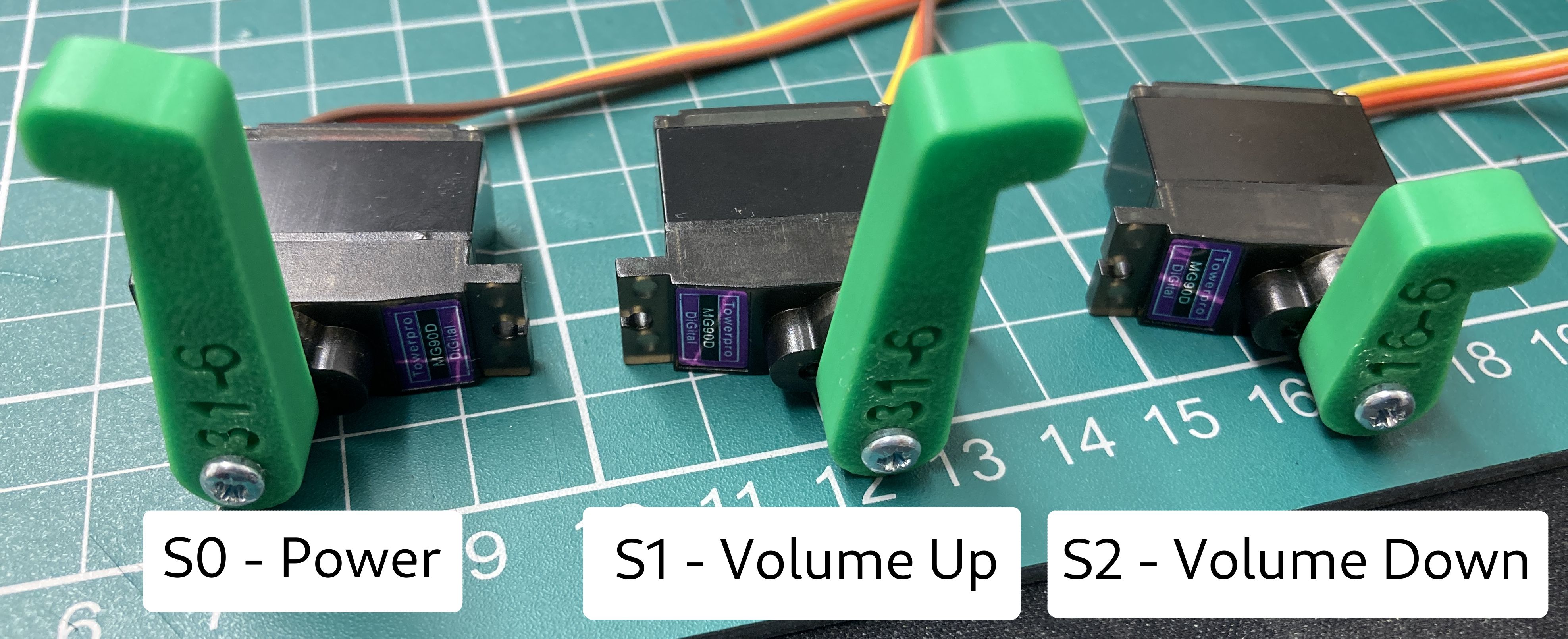
Servos
Before installing the servos into the phone jig the arms must be installed at a known position.
first connect up the servos as shown below:
Phone MIB |
Button |
Direction |
|---|---|---|
S0 |
Power |
Counter Clock Wise |
S1 |
Volume Up |
Clock Wise |
S2 |
Volume Down |
Clock Wise |
Then use the phone_mib_ctl tool to set the servos
laacli power 5v on
laacli power 12v on
phone_mib_ctl --config /share/lava/pixel6_mib_config.csv --action init
phone_mib_ctl --config /share/lava/pixel6_mib_config.csv --action manual_setup
Then attach the servo arm in an upright position facing the correct direction as shown below:
Servos setup
Once done turn the servos off:
phone_mib_ctl --config /share/lava/pixel6_mib_config.csv --action deinit
laacli power 12v off
laacli power 5v off
Jig Assembly
The files for 3d printing can be found here:
To assemble the jig you will need the following 3d printed parts:
4 x Servo ladders
1 x Phone carrier
7 x Phone hold caps
7 x Buffers
4 x Buffer ring
1 x Left LAA leg
1 x Right LAA legs
A selection of long and short M3 bolts and nuts.
A blend file showing the assembled device can be seen here:
The best way to make one is to get an existing one that has already been built so that you can copy it.
The following steps are a stream on conscious remembering of how the jig was assembled and is likely to be incorrect:
join the bottom 2 servo ladders using the 2 phone carrier straps
join the top 2 servo ladders using the Phone carrier.
Assemble the 4 servo holders for the servo ladders:
for the 2 taller mounts insert the buffer rings on before the buffer
slide the buffer on to the buffer mount
position on the phone hold down insert
place in servo ladder
place the servo hold down insert strap underneath the ladder
place the hold down cap on top
thread a bolt through all of them and attach a nut on the bottom
keep it a bit lose so you can move and reconfigure them as needed
put the phone on the phone holder screen up (this will put it at a slant)
position the phone holders (taller ones at the camera end)
construct and place the end holders in a similar way.
2 should be at the bottom either side of the usb port and 1 at the top
place the servos for power and volume up with shims as needed in the bottom rack
bolt the top rack on to the bottom.
place the volume down servo in the top rack
attach servo hold down arms to keep servo in place
Attach legs to LAA
Bolt jig to LAA
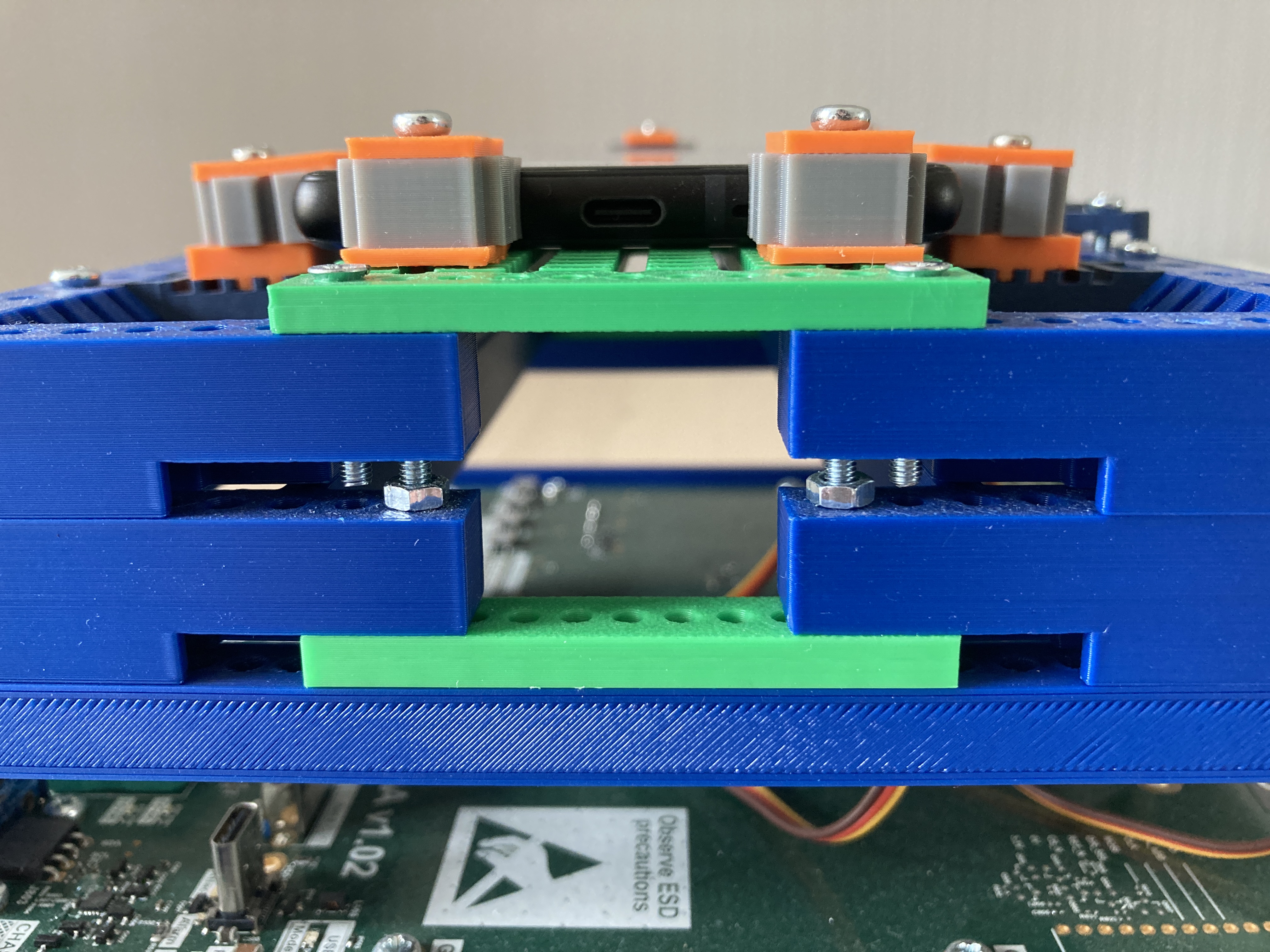
Pixel 6 jig end view
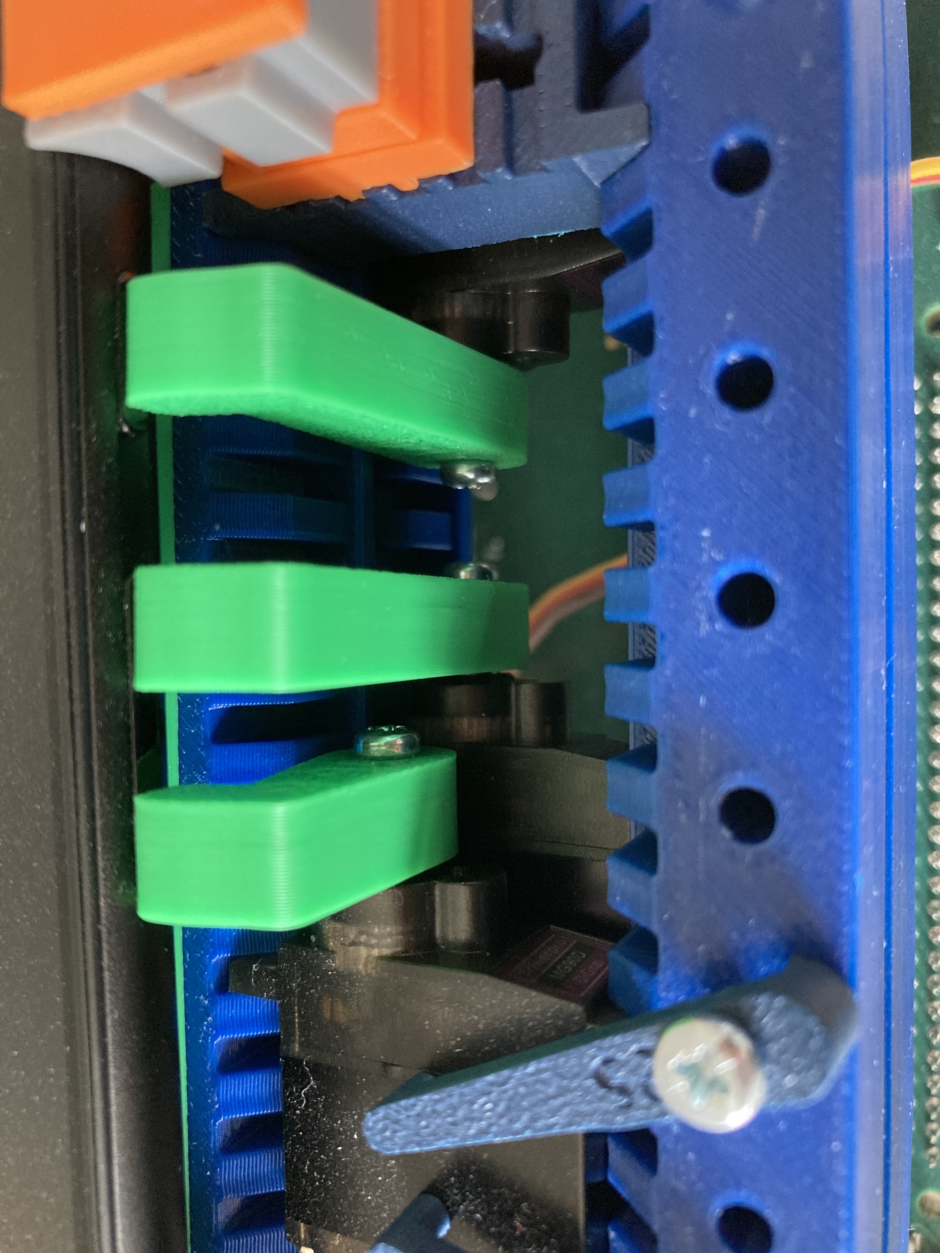
Pixel 6 jig servos installed
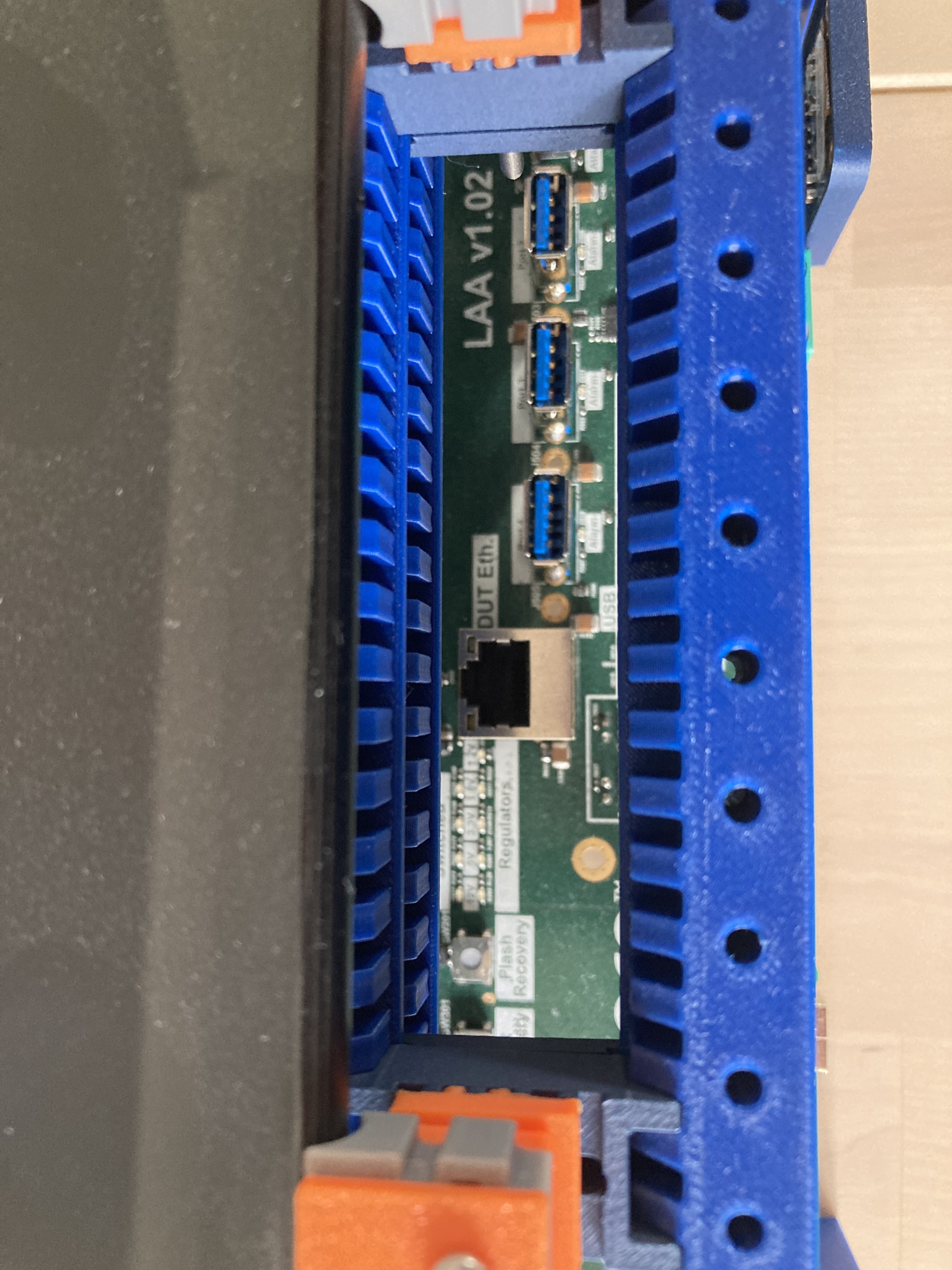
Pixel 6 LAA usb connectors must be accessible through the servo ladders
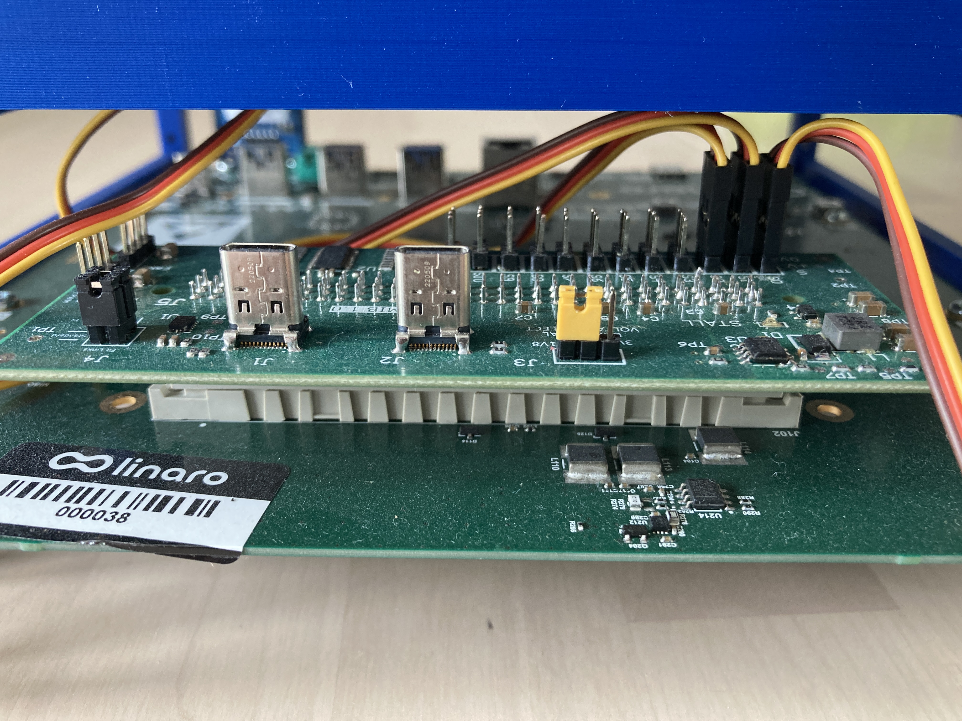
Pixel 6 MIB servo connections