Flylead
This MIB allow to connect and test any DUT as the MIB expose every connectors available.

Flylead MIB
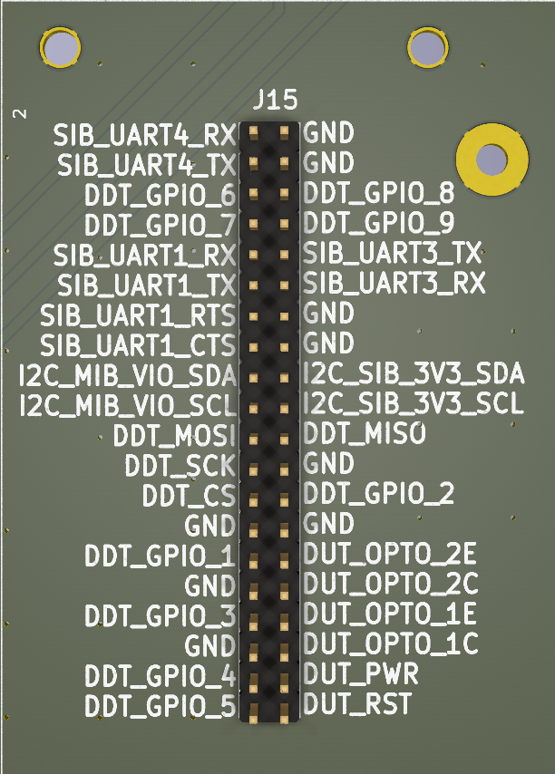
Flylead header
Header pinout
The flylead header pinout is defined as below:
A |
B |
|
|---|---|---|
1 |
SIB_UART4_RX |
GND |
2 |
SIB_UART4_TX |
GND |
3 |
DDT_GPIO_6 |
DDT_GPIO_8 |
4 |
DDT_GPIO_7 |
DDT_GPIO_9 |
5 |
SIB_UART1_RX |
SIB_UART3_TX |
6 |
SIB_UART1_TX |
SIB_UART3_RX |
7 |
SIB_UART1_RTS |
GND |
8 |
SIB_UART1_CTS |
GND |
9 |
I2C_MIB_VIO_SDA |
I2C_SIB_3V3_SDA |
10 |
I2C_MIB_VIO_SCL |
I2C_SIB_3V3_SCL |
12 |
DDT_MOSI |
DDT_MISO |
12 |
DDT_SCK |
GND |
13 |
DDT_CS |
DDT_GPIO_2 |
14 |
GND |
GND |
15 |
DDT_GPIO_1 |
DUT_OPTO_2E |
16 |
GND |
DUT_OPTO_2C |
17 |
DDT_GPIO_3 |
DUT_OPTO_1E |
18 |
GND |
DUT_OPTO_1C |
19 |
DDT_GPIO_4 |
DUT_PWR |
20 |
DDT_GPIO_5 |
DUT_RST |
USB ports
USB ports
The two USB ports on the flylead MIB are always ON and cannot be controlled from the software.
If you need a switchable USB port, use one of the 4 ports on the SIB.
Software usage
CAN
The CAN bus is available as can0 network interface. Use any CAN aware tools
like can-utils to interact on the bus.
GPIOs
Two gpios are available to toggle buttons. They can be controlled with:
laam laacli button reset on
laam laacli button reset off
The available GPIOs are:
DUT_RST:resetbuttonDUT_PWR:powerbutton
I²C
The header provides 2 I²C:
I2C_SIB_3V3_SCLandI2C_SIB_3V3_SDAat 3v3I2C_MIB_VIO_SCLandI2C_MIB_VIO_SDAatMIB_VIOreference voltage (from 0V to 5V).
Optocouplers
Two optocouplers are available to toggle on and off virtual buttons. The buttons can be controlled with:
laam laacli button 1 on
laam laacli button 1 off
The available optocouplers are:
DUT_OPTO_1CandDUT_OPTO_1E: virtual button1DUT_OPTO_2CandDUT_OPTO_2E: virtual button2
Power rails
Each power rail is available via screw terminal and can be controlled by laam:
laam laacli power 12v on
laam laacli power 12v off
laam laacli power 12v reset
The MIB provides access to the 4 power rails: 1v8, 3v3, 5v and 12v.
Delivered power
The power rail maximum power are listed in this table:
Power rail |
Max Amp (A) |
Max Power (W) |
|---|---|---|
1v8 |
1A |
1.8W |
3v3 |
2A |
6.6W |
5v |
3A |
15W |
12v |
3A |
36W |
Power rails power
The instant power consumption of each power rail is monitored and can be queried by laam:
laam laacli watt 12v
laam laacli watt 3v3
Serials
The header provides 3 set of serials:
SIB_UART1as/dev/ttycmx0: DUT serial with hardware flow controlSIB_UART3as/dev/ttycmx2: LAA serialSIB_UART4as/dev/ttycmx3: DUT serial
SIB_UART4 is also available via laam or telnet:
laam serials connect ttymxc3
telnet localhost 2000
SPI
The header provides one SPI: DDT_CS, DDT_SCK, DDT_MISO and DDT_MISO.