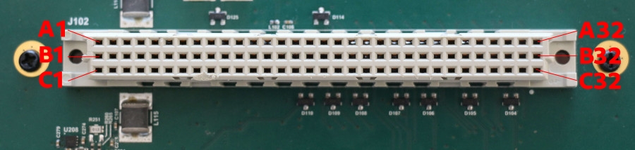
SIB header
The SIB header is a 3 rows and 32 pins header that connect the SIB to the MIB.
Reference Parts
SIB Header |
MIB Connector |
|
|---|---|---|
DigiKey Part Number |
||
Manufacturer |
TE Connectivity ERN |
HARTING |
Product Number |
254897-E |
09731962903 |
Description |
CONN DIN RCPT 96POS |
CONN DIN HDR 96POS |
Header pinout
The SIB header pinout is defined as below:
A |
B |
C |
|
|---|---|---|---|
1 |
GND |
GND |
GND |
2 |
+12V_SW |
+12V_SW |
+12V_SW |
3 |
GND |
GND |
GND |
4 |
+12V_SW |
+12V_SW |
+12V_SW |
5 |
GND |
GND |
GND |
6 |
+5V_SW |
+5V_SW |
+5V_SW |
7 |
GND |
GND |
GND |
8 |
+5V_SW |
+5V_SW |
+5V_SW |
9 |
GND |
GND |
GND |
10 |
+3V3_SW |
+3V3_SW |
+3V3_SW |
11 |
GND |
GND |
GND |
12 |
+1V8_SW |
+1V8_SW |
+1V8_SW |
13 |
+12V |
+3V3 |
+1V8 |
14 |
GND |
GND |
GND |
15 |
DUT_OPTO_4C |
+5V |
I2C_SIB_3V3_SCL |
16 |
DUT_OPTO_3C |
GND |
I2C_SIB_3V3_SDA |
17 |
DUT_OPTO_2C |
MIB_VIO |
DUT_OPTO_2E |
18 |
DUT_OPTO_1C |
GND |
DUT_OPTO_1E |
19 |
DUT_RST |
DDT_CS |
I2C_MIB_VIO_SCL |
20 |
DUT_PWR |
DDT_SCK |
I2C_MIB_VIO_SDA |
21 |
GND |
DDT_MISO |
GND |
22 |
DDT_GPIO_9 |
DDT_MOSI |
SIB_UART1_CTS |
23 |
DDT_GPIO_8 |
GND |
SIB_UART1_RTS |
24 |
DDT_GPIO_7 |
SIB_USB_H2_DM |
SIB_UART1_TX |
25 |
DDT_GPIO_6 |
SIB_USB_H2_DP |
SIB_UART1_RX |
26 |
GND |
GND |
GND |
27 |
DDT_GPIO_5 |
SIB_USB_H1_DM |
SIB_UART3_TX |
28 |
DDT_GPIO_4 |
SIB_USB_H1_DP |
SIB_UART3_RX |
29 |
DDT_GPIO_3 |
GND |
GND |
30 |
DDT_GPIO_2 |
DDT_CAN_L |
SIB_UART4_TX |
31 |
DDT_GPIO_1 |
DDT_CAN_H |
SIB_UART4_RX |
32 |
GND |
GND |
GND |
Header orientation
When using hardware design tools, the model for the SIB header is labeled the over way around!
Software usage
CAN
The CAN bus is available as can0 network interface. Use any CAN aware tools
like can-utils to interact on the bus.
GPIOs
Two gpios are available to toggle buttons. They can be controlled with:
laam laacli button reset on
laam laacli button reset off
The available GPIOs are:
DUT_RST:resetbuttonDUT_PWR:powerbutton
I²C
The header provides 2 I²C:
I2C_SIB_3V3_SCLandI2C_SIB_3V3_SDAat 3v3I2C_MIB_VIO_SCLandI2C_MIB_VIO_SDAatMIB_VIOreference voltage (from 0V to 5V).
Optocouplers
Two optocouplers are available to toggle on and off virtual buttons. The buttons can be controlled with:
laam laacli button 1 on
laam laacli button 1 off
The available optocouplers are:
DUT_OPTO_1CandDUT_OPTO_1E: virtual button1DUT_OPTO_2CandDUT_OPTO_2E: virtual button2
Unused pins
DUT_OPTO_3C and DUT_OPTO_4C are not used.
Power rails
The power pins, flagged with _SW, are managed power rails that can be
controlled by laam:
laam laacli power 12v on
laam laacli power 12v off
laam laacli power 12v reset
The header provides 4 power rails: 1v8, 3v3, 5v and 12v.
Delivered power
The power rail maximum power are listed in this table:
Power rail |
Max Amp (A) |
Max Power (W) |
|---|---|---|
1v8 |
3A |
5.4W |
3v3 |
3A |
9.9W |
5v |
5A |
25W |
12v |
7.5A |
90W |
Over Current Protecting
As mentioned in the table above, the LAA should not deliver more than 7.5A.
The LAA runs a software (soft) and hardware (hard) Over Current Protecting (OCP) mechanism to protect the LAA and the attached DUT if the DUT draw more power than expected.
If soft OCP is triggered, the power rails will be shutdown and a message will be printed on every telnet and ssh sessions.
If hard OCP is triggered, the LAA will be shutdown immediately.
The soft OCP should be triggered faster than the hard OCP but under some circumstances, the hard OCP might be triggered anyway.
Power rails power
The instant power consumption of each power rail is monitored and can be queried by laam:
laam laacli watt 12v
laam laacli watt 3v3
Serials
The header provides 3 set of serials:
SIB_UART1as/dev/ttycmx0: DUT serial with hardware flow controlSIB_UART3as/dev/ttycmx2: LAA serialSIB_UART4as/dev/ttycmx3: DUT serial
SIB_UART4 is also available via telnet:
SIB_UART4 is also available via laam or telnet:
laam serials connect ttymxc3
telnet localhost 2000
SPI
The header provides one SPI: DDT_CS, DDT_SCK, DDT_MISO and DDT_MISO.
USBs
The header provide 2 USB ports that are always on at:
SIB_USB_H1_DMandSIB_USB_H1_DPSIB_USB_H2_DMandSIB_USB_H2_DP