BeagleBoard-X15
Enablement
LAVA by default is configured to work with this DUT + LAA setup. If you opt for a different setup you’ll have to change your DUT + LAA device configuration on LAVA.
The BeagleBoard-X15 is an open hardware single board computer built around the TI AM5728, a dual Cortex-A15 SoC with 2 GiB of RAM, two gigabit ethernet ports and eMMC. On an LAA it runs from the 12V rail through a flylead MIB.
The board doesn’t start when power is applied. The S1 power button has to be pressed, and there is no header in parallel with it, so this device-type needs a small hardware modification.
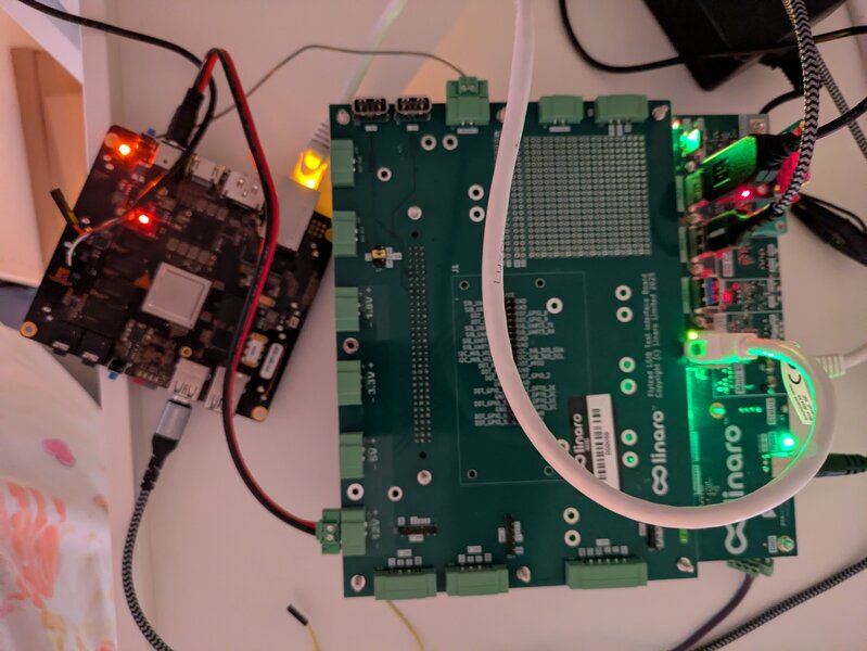
Components
The following components are required to fully automate the board:
Short RJ45 network cable
2.5/5.5mm barrel jack to MIB 2-pin connector, wired center positive
USB-TTL serial cable with 3.3V logic, for example a PL2303 or an FTDI TTL-232R-3V3
USB-A male to Micro-B male cable, for fastboot recovery (optional)
Two wires soldered across S1, and a soldering iron to fit them
Hardware modification
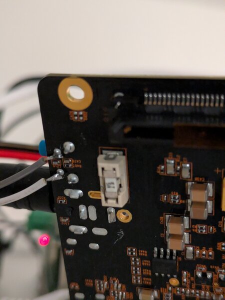
The X15 doesn’t power on when 12V is applied. S1 has to be pressed, and the board exposes no header or pad in parallel with it. Solder one wire to each contact of S1, the blue tactile switch on the board edge next to the F1 fuse.
Find the two contacts with a multimeter first: the pair that’s open at rest and closes when the button is pressed. Add strain relief, the joints are small and the wires get pulled every time the board moves.
MIB
Configuration
No MIB voltage jumper is needed. The USB-TTL cable carries its own 3.3V logic,
so MIB_Vio and the J17 jumper aren’t part of this setup.
If you instead use the MIB UART on J12, set J17 to 3v3 and turn the 3v3
rail on, because MIB_Vio is fed from the switched 3v3 rail.
Power
The X15 gets 12V from the J2 screw terminal on the MIB, out to a 2.5/5.5mm
barrel jack in P1 on the board, wired center positive.
Then press S1 through virtual button 1. The press must be short: button 1 on
immediately followed by button 1 off. A held press starts the board and then
powers it off again on release. The press also doesn’t register if it lands
within a second or so of the rail coming up, so leave a short delay.
Serial
Connect the USB-TTL cable to the P10 header:
Cable wire |
|
Signal |
|---|---|---|
black |
1 |
GND |
green |
4 |
board RX, cable transmit |
white |
5 |
board TX, cable receive |
red |
- |
5V, leave unconnected |
The board is powered from P1, so the red 5V wire stays off.
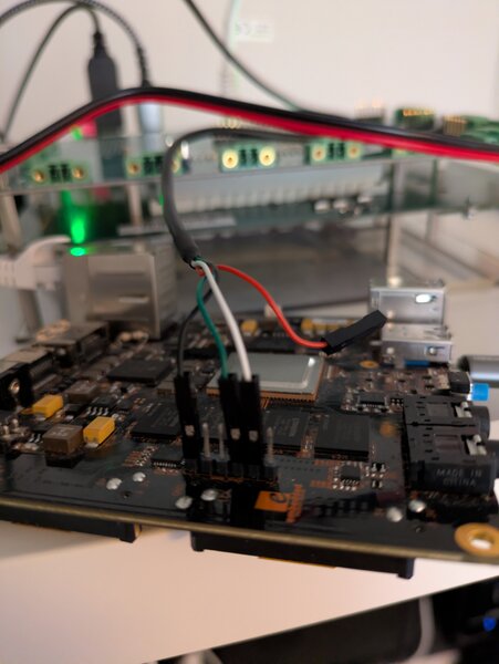
Plug the cable into LAA USB Port2. The console comes up as ttyUSB0 at
115200 8N1 on port 2010. Turn the port on with laacli usb 2 on and leave it
on, the device node disappears with the port.
Network
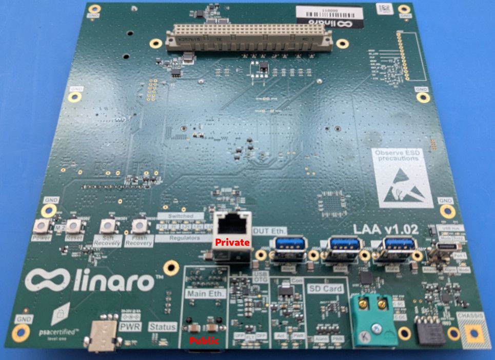
Connect one of the two stacked RJ45 ports on P5 to the LAA private network
interface.
Only one of the two ports works
U-Boot brings up a single interface, eth2 on ethernet@48484000. The other
port never links. If you pick the wrong one you get
Waiting for PHY auto negotiation to complete... TIMEOUT ! on every boot
attempt and the boot takes minutes instead of seconds.
When it is right you get link up on port 0, speed 1000, full duplex and the
board is given 198.18.0.2 by the LAA.
Recovery
Connect the X15 micro-USB port to LAA USB Port3 with a data cable. The board
enumerates as a TI USB download gadget, 0451:d022. Turn the port on with
laacli usb 3 on when you need fastboot.
It’s not needed to reach the bootloader.