I-Pi SMARC IMX8M Plus
Enablement
LAVA by default is configured to work with this DUT + LAA setup. If you opt for a different setup you’ll have to change your DUT + LAA device configuration on LAVA.
This document applies to the following boards:
I-Pi SMARC IMX8M Plus: imx8mp-ipi-lec
Components
The following components are required to fully automate the board:
Short RJ45 network cable
2.5/5.5mm barrel jack to MIB 2-pin connector, wired centre positive
USB type A to USB micro B cable
USB type A to USB type C cable
USB to RS232 adapter, with male DB9 connector
Board modifications
The carrier board requires a modification to allow LAVA to switch the device into, and out of, USB recovery download mode. The modification must be applied to the DIP switch that is used to select the boot mode.
The DIP switch is labeled SW1401 in the schematic diagram but it is not marked on the silk screen. SW1401 is located behind the network sockets and is shown in the following diagram.
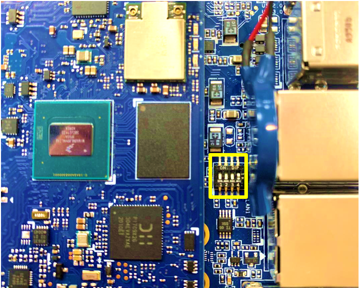
The fourth switch, labeled 4 in the above diagram, requires flying leads to be solderd to both sides and brought out to the edge of the board.
Connections
Overview
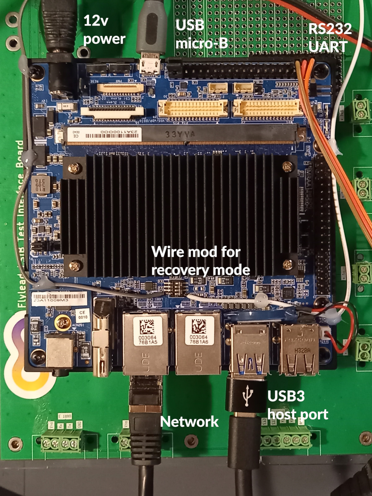
The diagram below shows the device-under-test with all six connections installed, including the wires for the board modification above:
From flylead MIB to DUT
Disconnect the IO voltage jumper (J17) on the flylead MIB. This has no functional effect but since I/O header we recommend disabling it.
Ensure SW1401-4 is in the off position, then connect the SW1401-4 flyleads to V Button 1 on the right edge of the flylead MIB
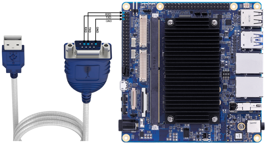
Connect a USB to RS-232 adapter to USB 1 socket of flylead MIB. Connect GND, TX and RX to the 40-pin expansion header (located next to micro-USB connector). Connect DB9 pin 2 to expansion header pin 3, DB9 pin 3 to pin 1 and DB9 pin 5 to pin 5 (as diagram below).
Connect USB micro-B (CN1304, located near the power connector) to USB 2 socket of flylead MIB
From SIB to DUT
Connect LAN1 (located next to the HDMI connector) to DUT Eth on the LSIB
Connect USB type A (bottom connector of the USB3 stack) to USB OTG on the LSIB
Software
No Software setup is required for this board. When configured as above the board can be automatically provision from scratch.