LAA on LAA
Enablement
LAVA by default is configured to work with this DUT + LAA setup. If you opt for a different setup you’ll have to change your DUT + LAA device configuration on LAVA.
The LAA DUT can be automated using the Flylead MIB.
Components
The following components are required to fully automate the board:
LoL DUT v2 Board
Short RJ45 network cable
USB-A male to USB-C male cable
USB-A male to USB-A male cable
5x Cable Pairs
2x 18AWG or better for power rails.
Hardware Modifications
In order to automate recovery, the DUT hardware should be modified.
Hardware modification
The DUT will not be automatizable without this modification.
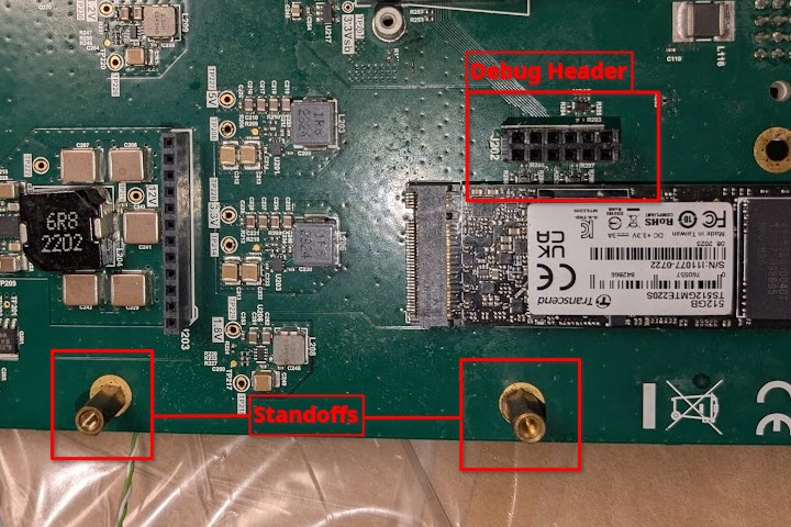
Debug header
A 2x6 pin 2.54mm Female header needs to be soldered next to the NVMe SSD at J202. This is used to trigger flash recovery from the LAA-Worker without the need to solder wires directly to the push buttons.
Standoffs
The two standoff close to J202 and J203 need to be removed and ideally be replaced with a 11mm high standoff in order to secure the LoL DUT v2 Board in place.
HW modification
LAA on LAA DUT Board v2
The LoL Board v2 provides:
Power to the LAA-DUT from the LAA-Worker using LAA-DUT’s PoE Header
Breakout LAA-DUT’s Power, Reset and Flash Buttons from the Debug Header (we are only using the flash Button)
USB switching of LAA-DUT’s OTG port between Host and Gadget mode between LAA-Worker and a Raspberry Pi DUT may be installed on the LAA-DUT.
Installation
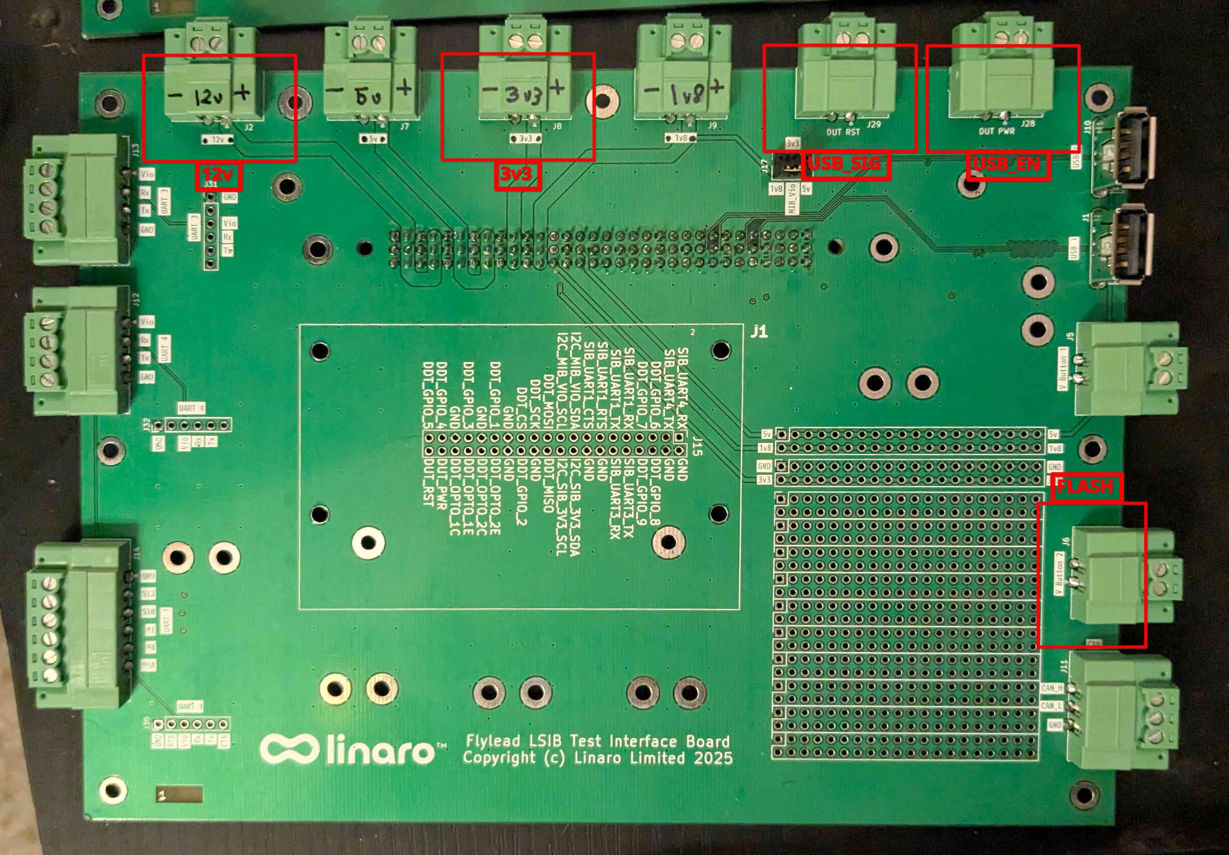
Taking care of the polarity install wire pairs for the following screw terminals
12v
3v3
Flash
USB_EN
USB_SIG
Carefully install the LoL Board on to the LAA-DUT as shown below. The debug header and PoE header should be inserted into their respective headers on the LoL board. Make sure that the placement is correct.
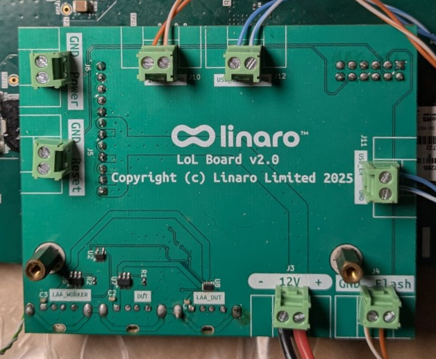
LoL Board v2
MIB
We need to now connect the wires from the LoL Board to the Flylead MIB on the LAA-Worker and set the MIB_VIO Jumper to 3v3.
12v to 12v, take care of plarity.
3v3 to 3v3, take care of plarity.
FLASH to V_Button_2, polarity does not matter
USB_SIG to DUT_RST, take care of polarity the signal pin has a
^marking.USB_EN to DUT_PWR, take care of polarity the signal pin has a
^marking.
Flylead Connections
Ports
Connect the following ports.
LAA-Worker USB Port 4 to LoL Board LAA_Worker USB Port.
LAA-DUT OTG Port to LoL Board LAA-DUT USB Port.
LAA-Worker Ethernet Port 2 to LAA-DUT Ethernet Port 1.