Assembling
In this document we will be going through the main practical steps to put together a Linaro Automation Appliance (LAA). As an example we will consider as Device Under Test (DUT) a Raspberry PI 4 Model B (RPi 4B)
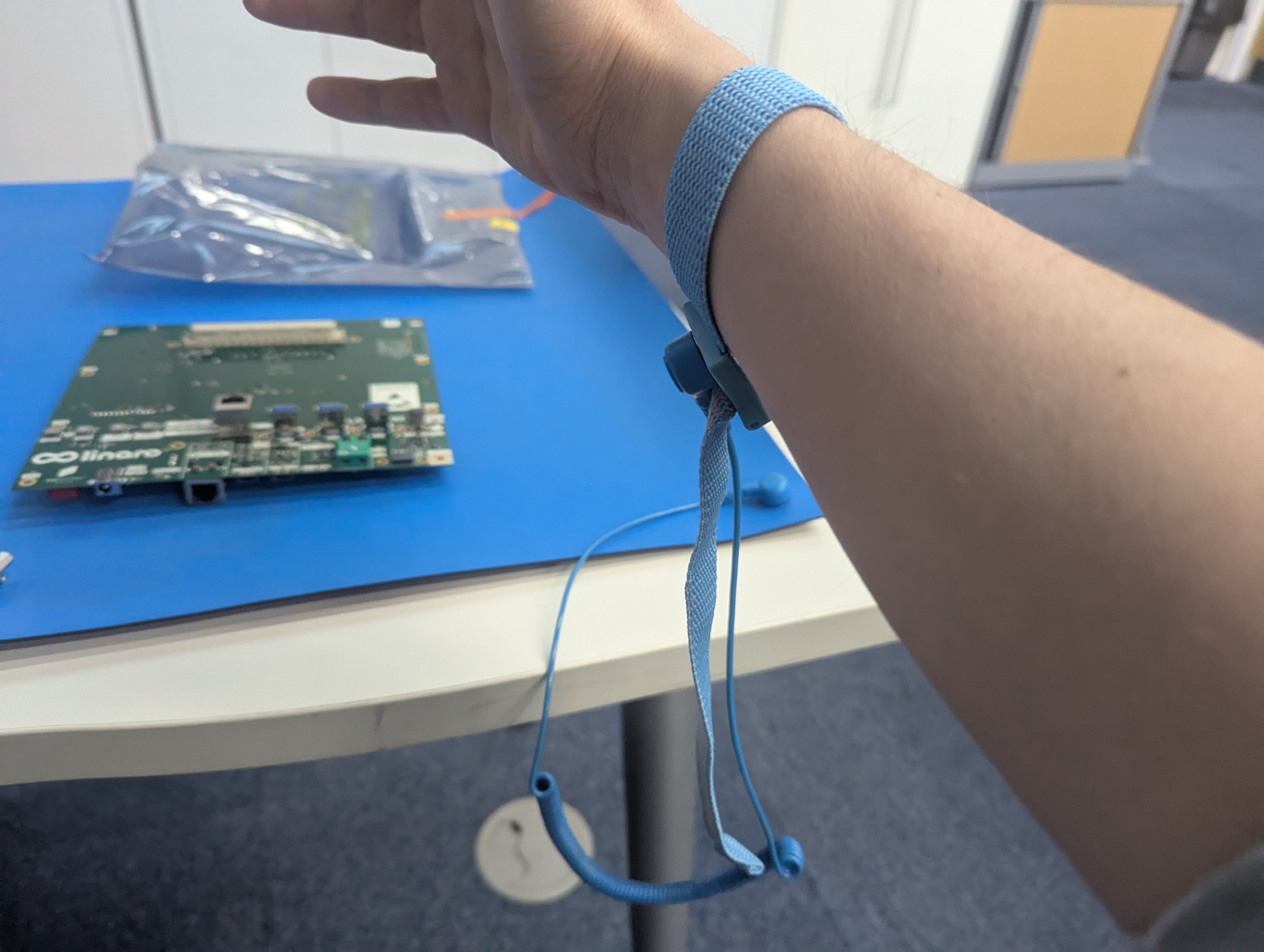
It is suggested to make use of an anti-static mat and also wear the anti static wrist strap. Please remember to connect the mat and the strap to the ground.
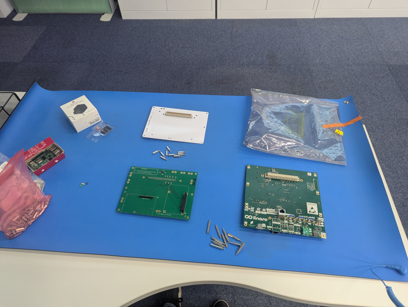
Here is a list of what we need:
Standard Interface Board (SIB)
Mechanical Interface Board (MIB)
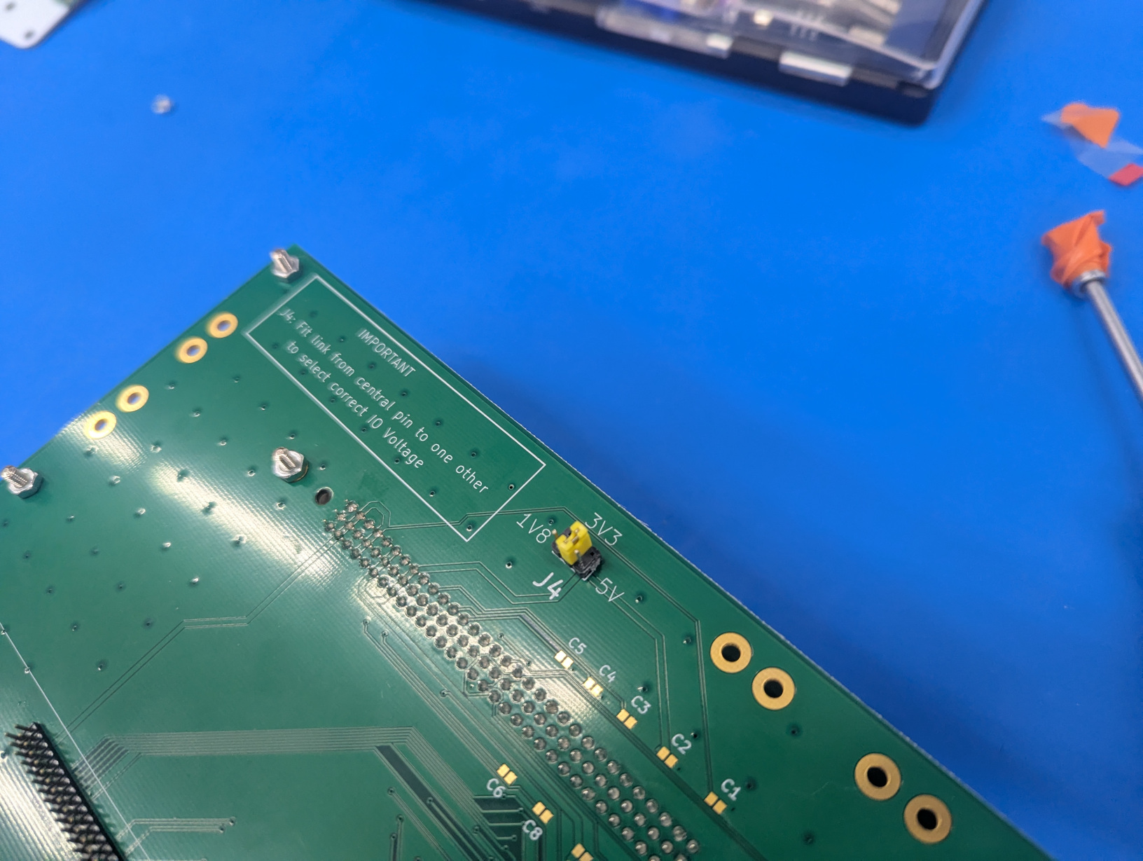
Jumper for the 3v3 pin
Raspberry:
Raspberry PI Model 4B
32 GB SD Card
(optionally) x4 M3 plastic screws
(optionally) x4 17mm M3 brass spacers
(optionally) x4 M3 hex nuts
Temperature Sensor
Supports:
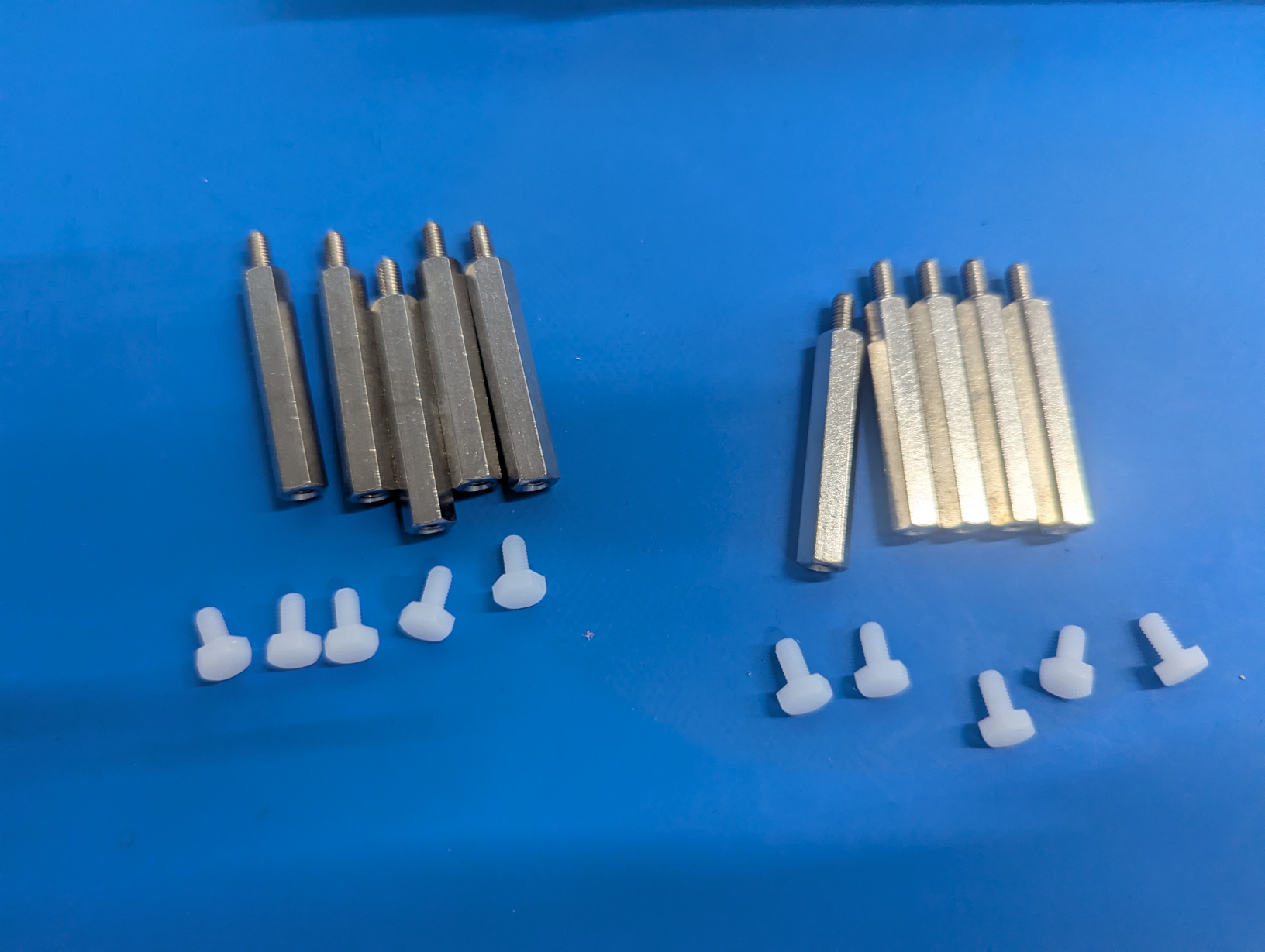
x10 30mm M3 brass spacers
x10 M3 plastic screws
x8 17mm M3 brass spacers
x8 M3 hex nuts
x4 30mm M2 brass spacers
x10 M3 plastic screws
(Optionlly ) 1x Linaro LAA Support Base
Mini Screen:
OLED
OLED protector
x2 M3 screws
x2 M3 hex nuts
Supports for the SIB
The first thing we want to do is to assemble the supports on the SIB so that it can stand safely.
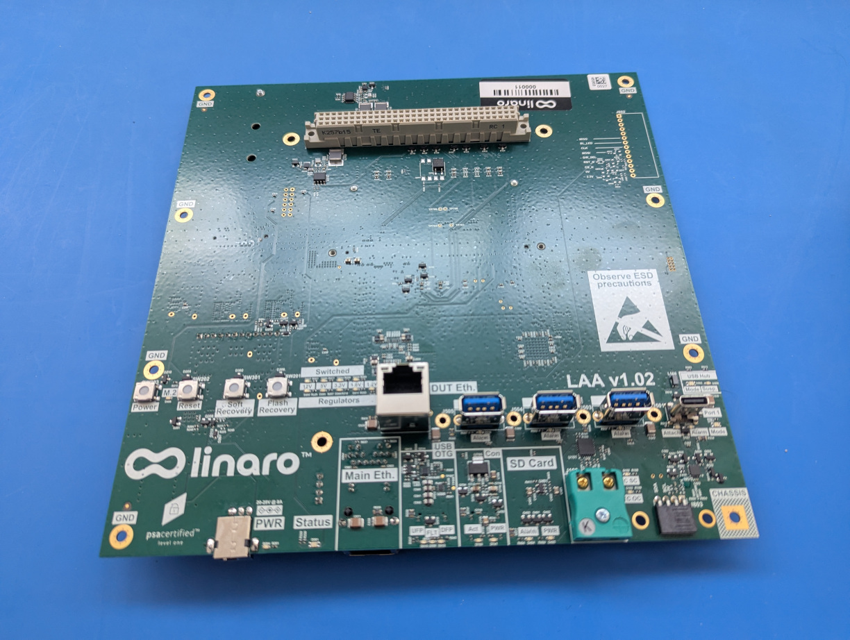
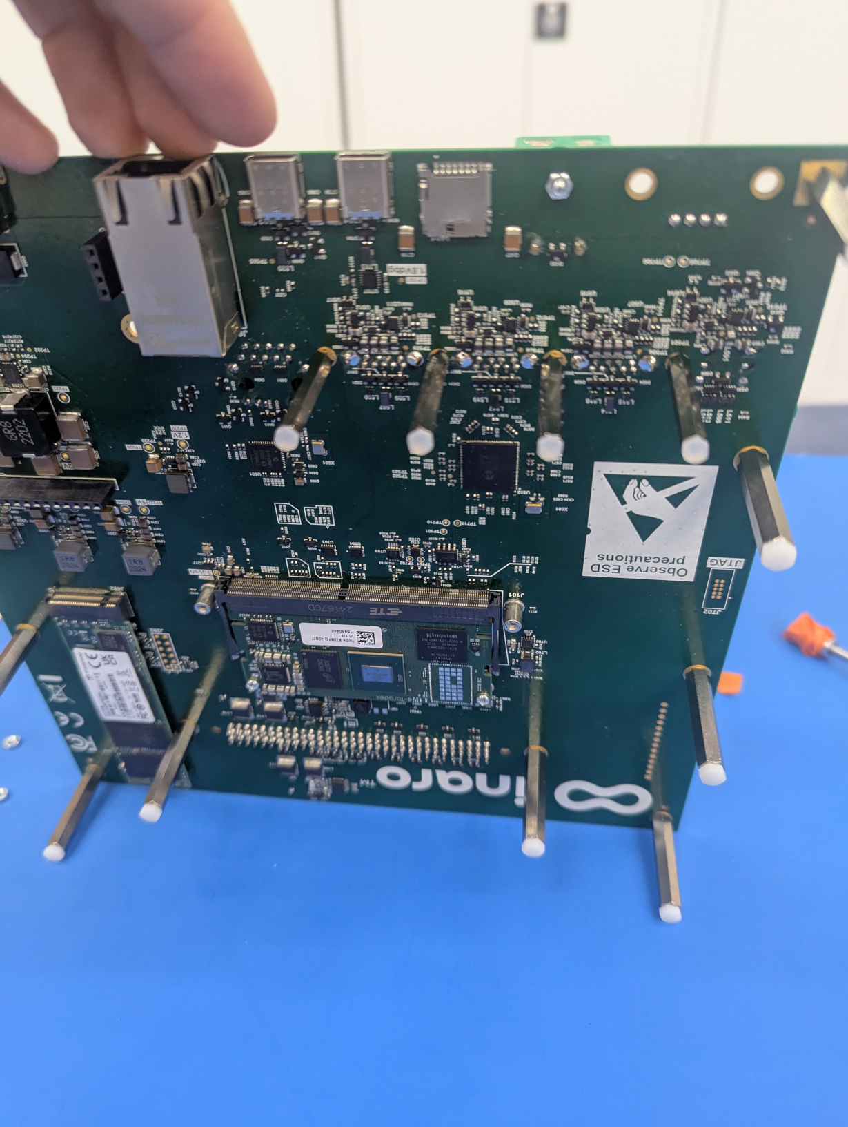
This is what a SIB looks like, specifically an hardware revision 3 board:
We want to add the longer 30mm spacers at the bottom. But first we want to add “feet” to the spacers, which will be the plastic M3 screws.
Linaro LAA Support Base
If you have Linaro LAA Support Base make use of it to place your 30mm spacers. It will be very easy to place the SIB on top and fix it.
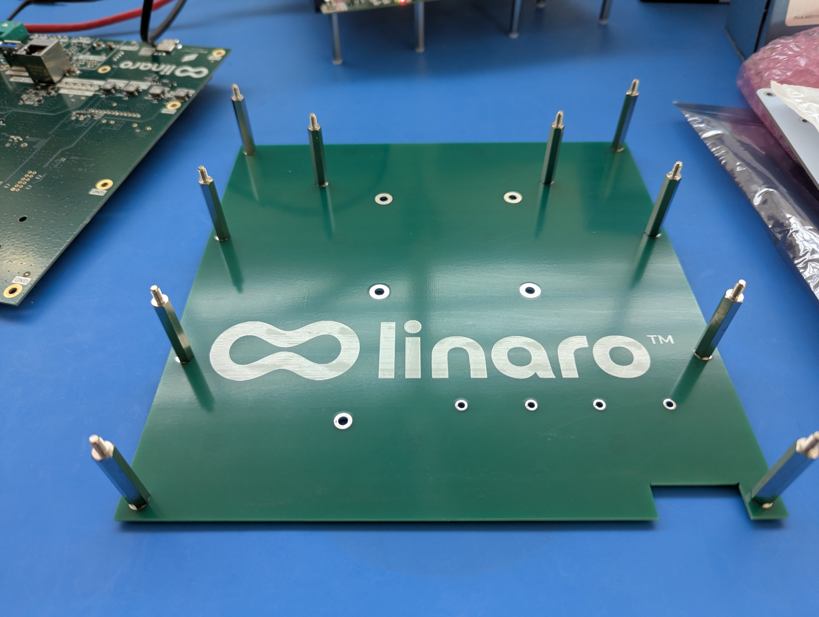
The 30mm spacers will need to be screwed on the other side of the board with the 17mm spacers or with an hex hut, as you can see here:
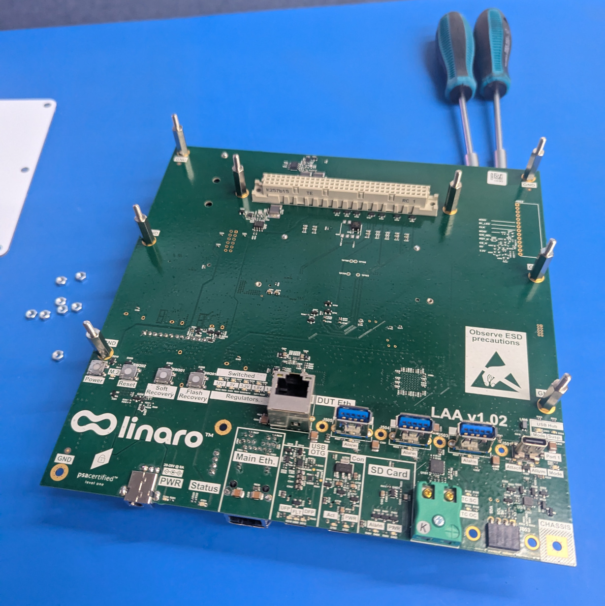
In the next photo you can see where you want to put 8 of the supports (the other 2 will be just afterwards):
For the last 2 30mm spacers we will be using hex nuts, these will be placed at the front of the SIB.
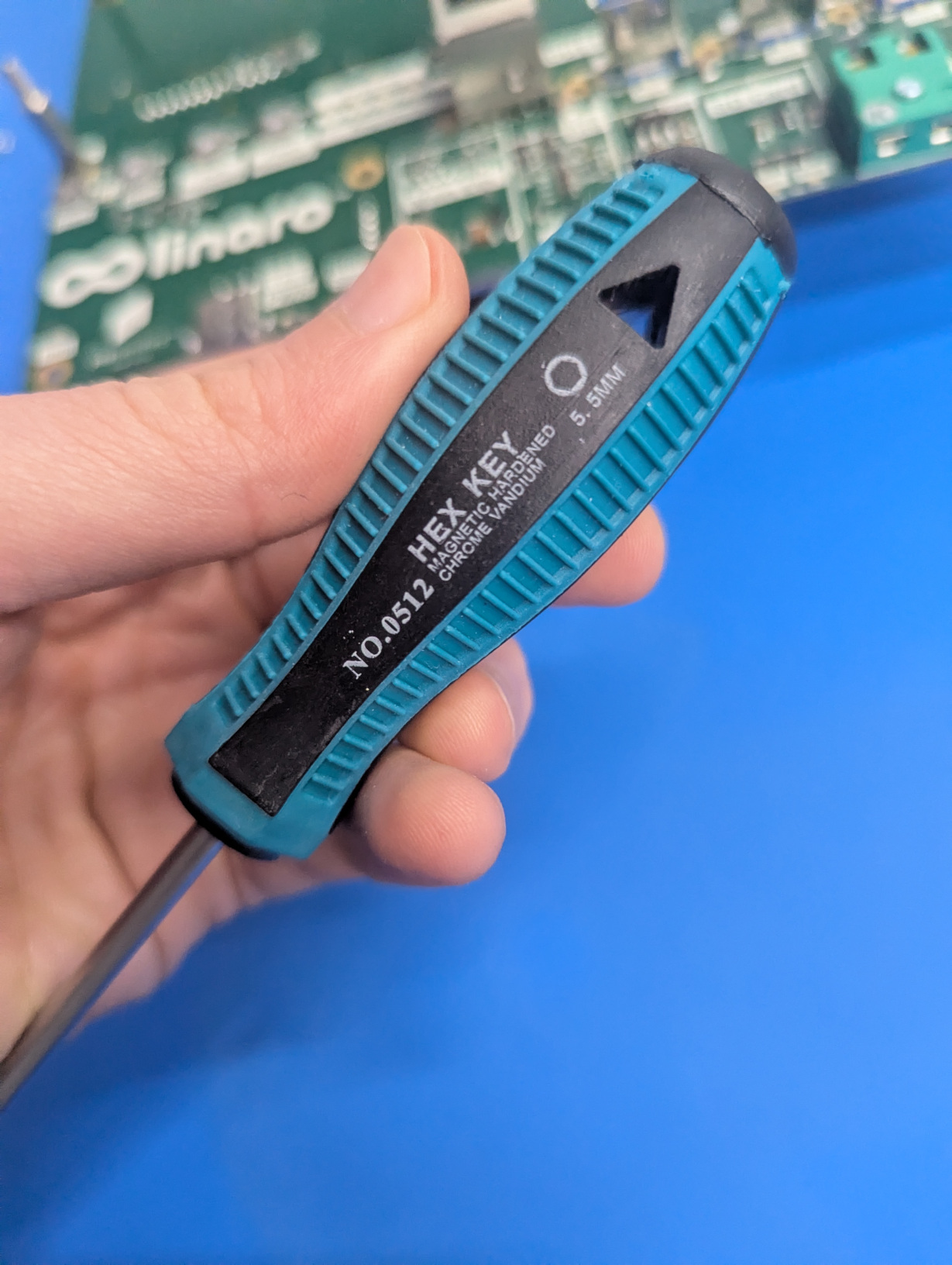
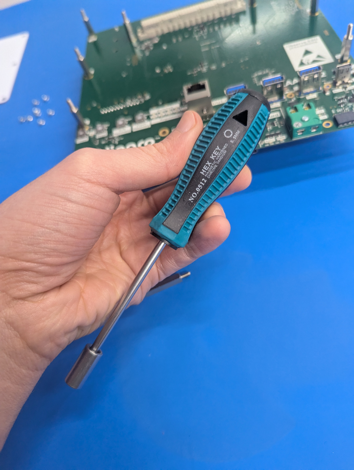
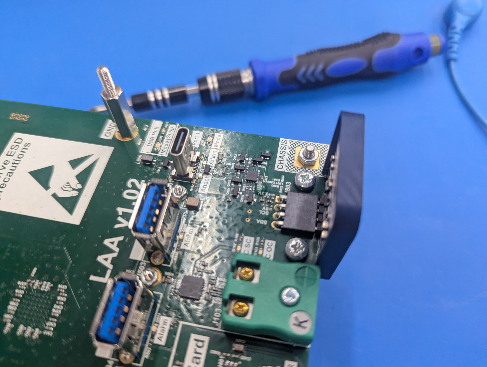
Please make use of a hex wrench (next photo) to make sure everything is properly fixed.
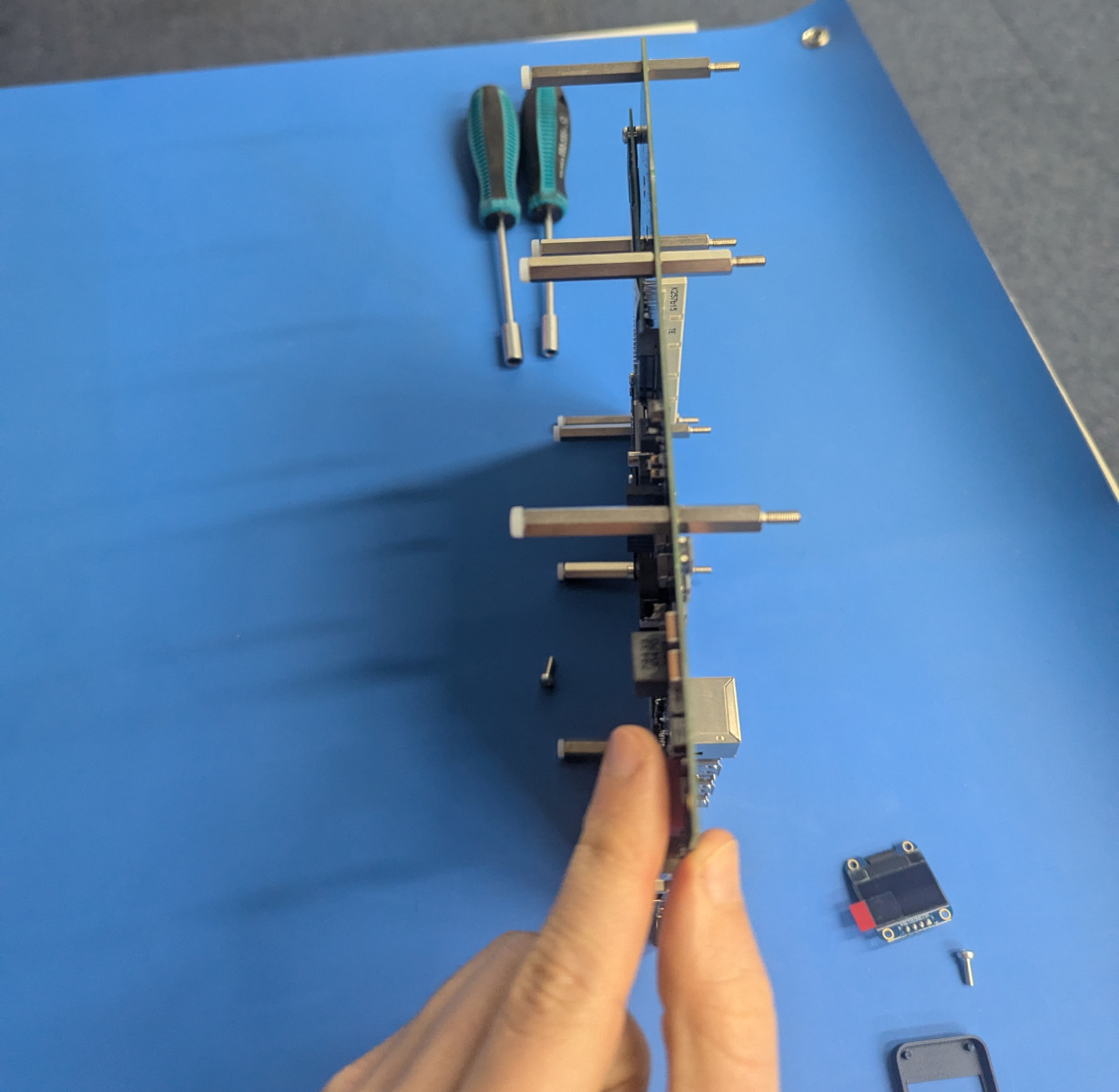
At this point we want to add the M2 30mm spacers underneath the USB plugs. These are very important to avoid for the SIB board to bend and break when someone wants to plug USB connectors to them.
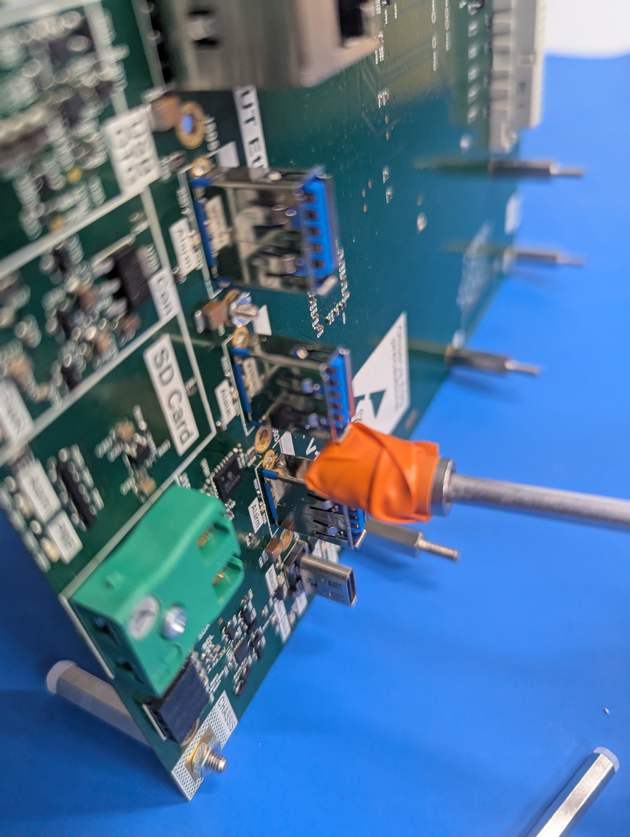
As you will see the holes are between the USB plugs, making it harder to mount the supports. Your fingers will be too big to place the hex nut between the plugs. The best way would be to make use of a hex wrench that is also magnetic, making the nut stick on the tool. Otherwise a trick is to take some tape and put it around the wrench, then we want to attach the hex nut to it. You can see it here:
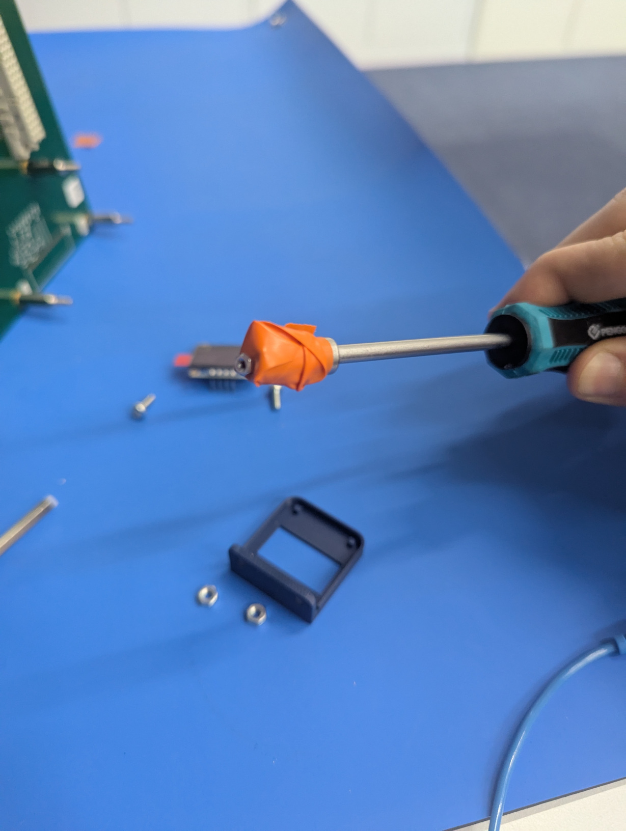
You can put the hex nut in front of the hole between the USB plugs and then screw the spacer from the other side.
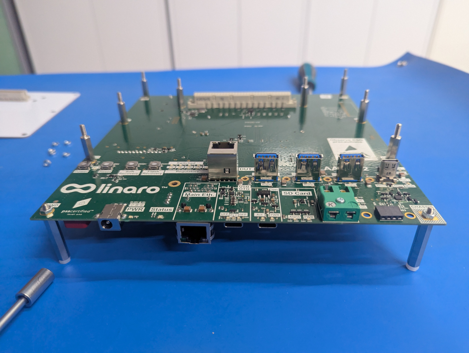
That’s what you should be seeing after mounting these 4 supports.
Use the hex wrench to make sure all the M3 plastic “feet” are properly screwed.
SIB feet
The M2 30 mm spacers will have smaller M2 plastic screw “feet”. In order to touch the ground they need to NOT be fully screwed. This will ensure to not bend the SIB board when you try to connect something on the USB plugs.
OLED Screen
It is now time to mount the OLED screen. There is an optimal sequence of steps to mount it easily.
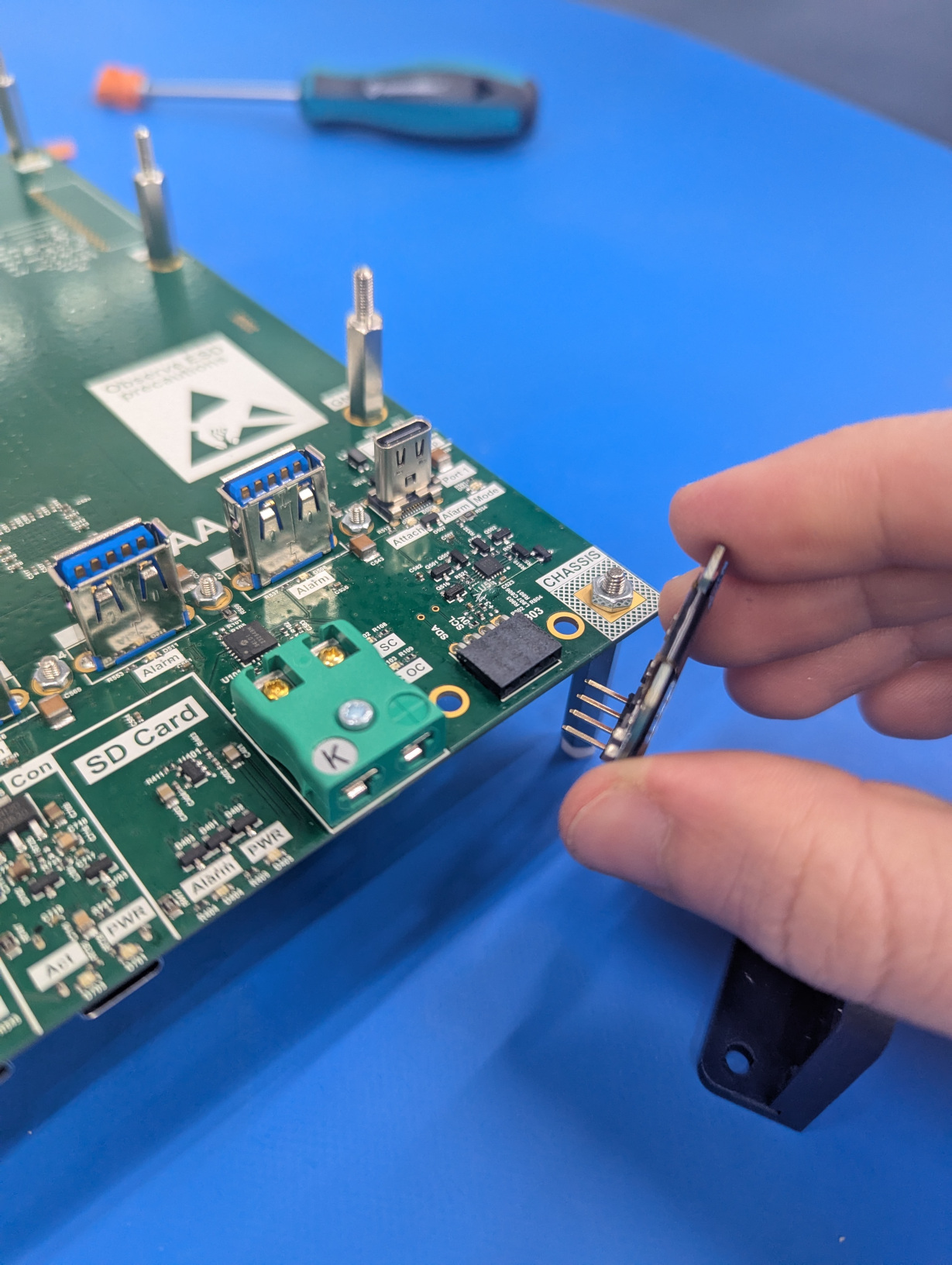
First, we want to insert the OLED screen component on the 4 pin connector.
Then we want to put the protector in front of the OLED.
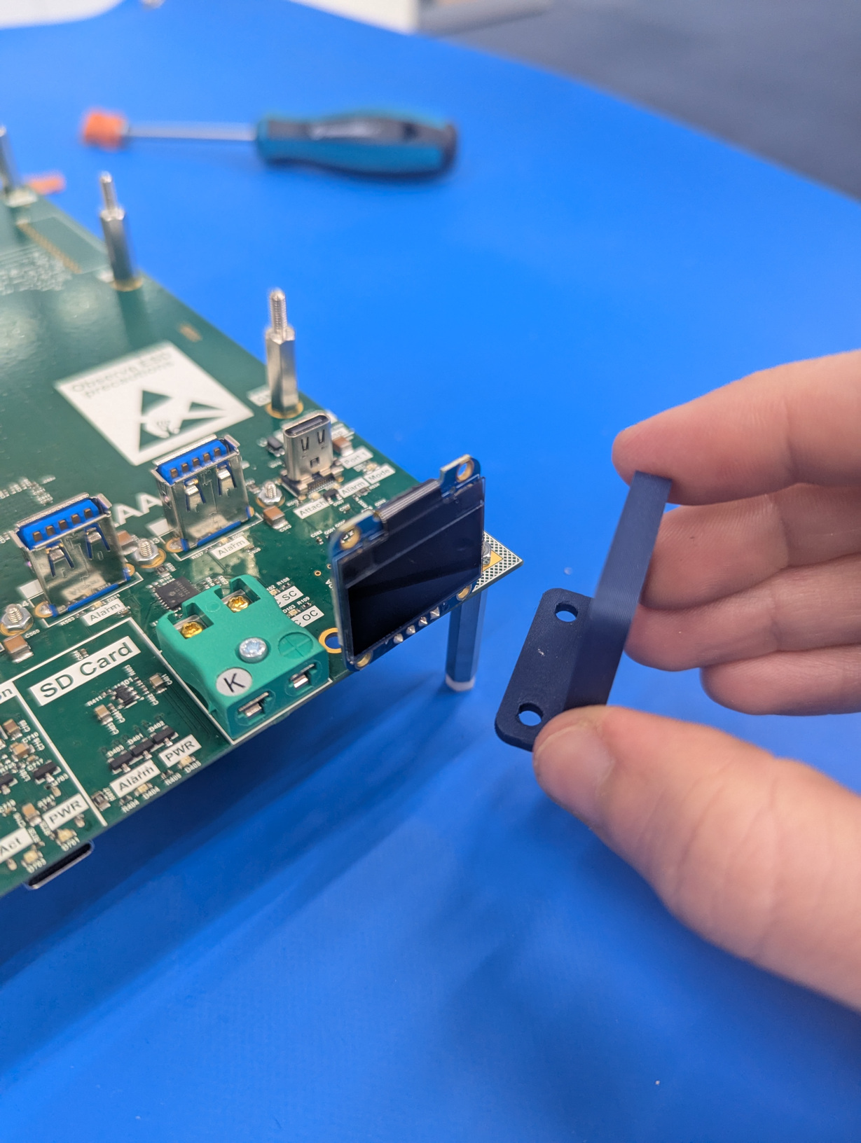
Protector
The bottom part of the protector will go on the other side of the SIB board.
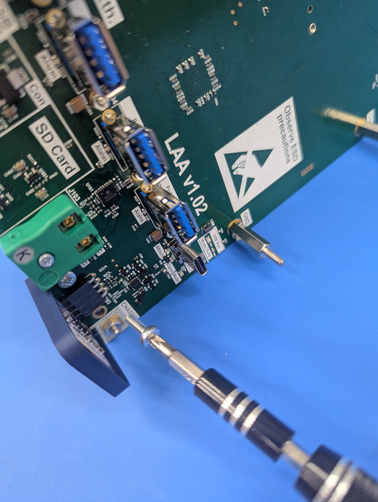
Finally, we want to put the screws with the nuts.
Temperature Sensor
Mounting the temperature sensor is straightforward since there is once one place it can go and cannot be inserted in the wrong way.
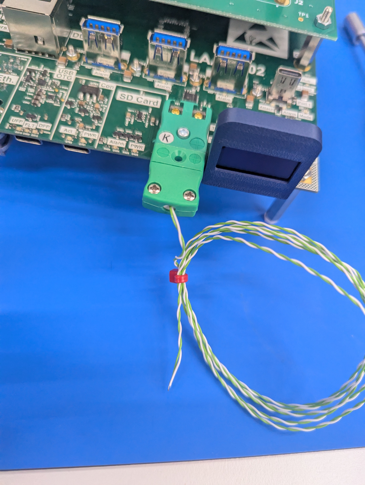
Sensor
The sensor itself is at the end of the wire, you can decide where you want to place it and read values from.
Adding the MIB
At this point the SIB is ready to have the MIB placed on top.
But before, you can optionally add supports for the DUT board on the MIB. In order to do so you need to find appropriate spacers and the hex nuts and screws to fix them. Double-check where the holes are.
Spacers
The spacers are probably going on the top of the MIB.
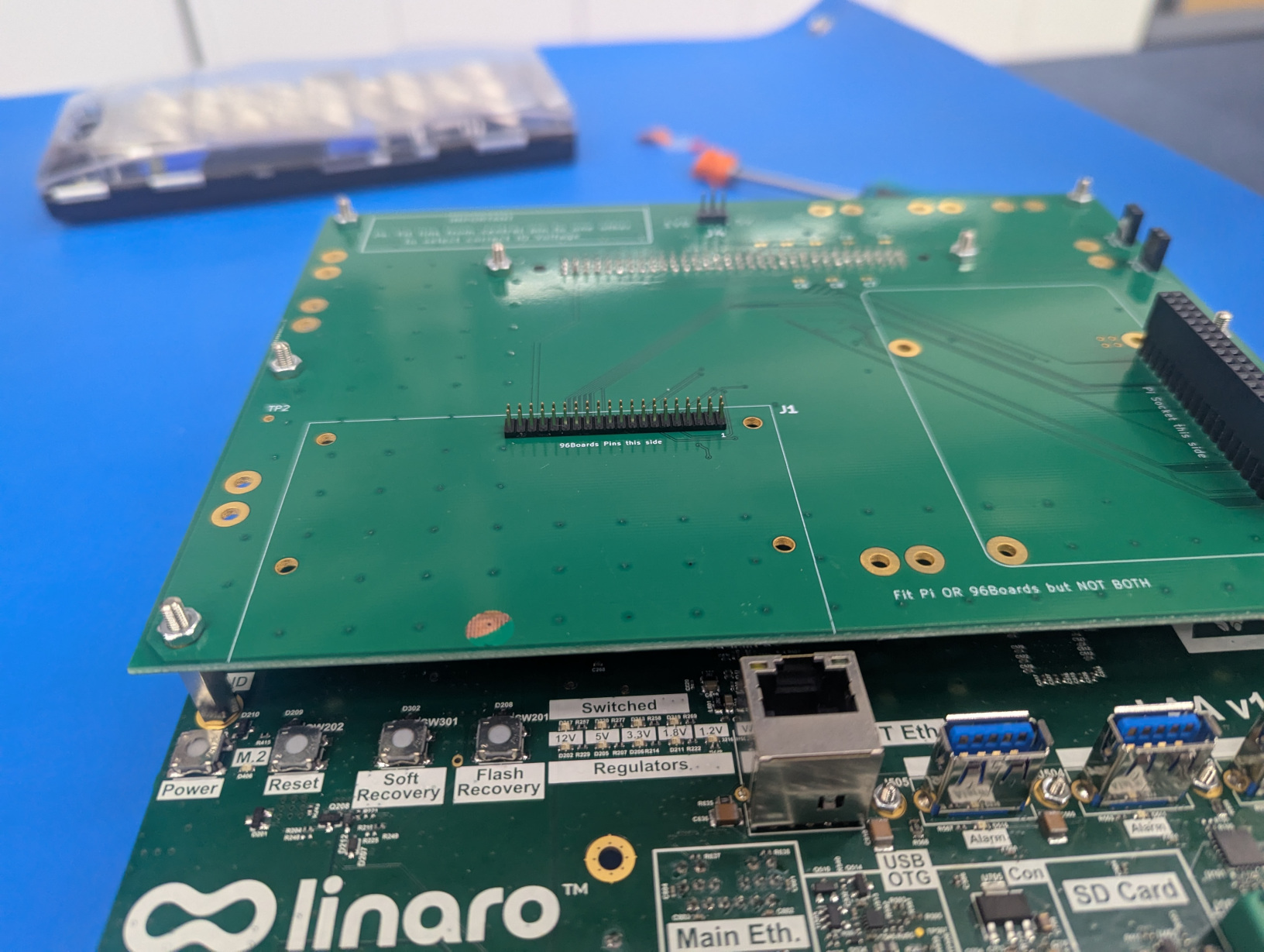
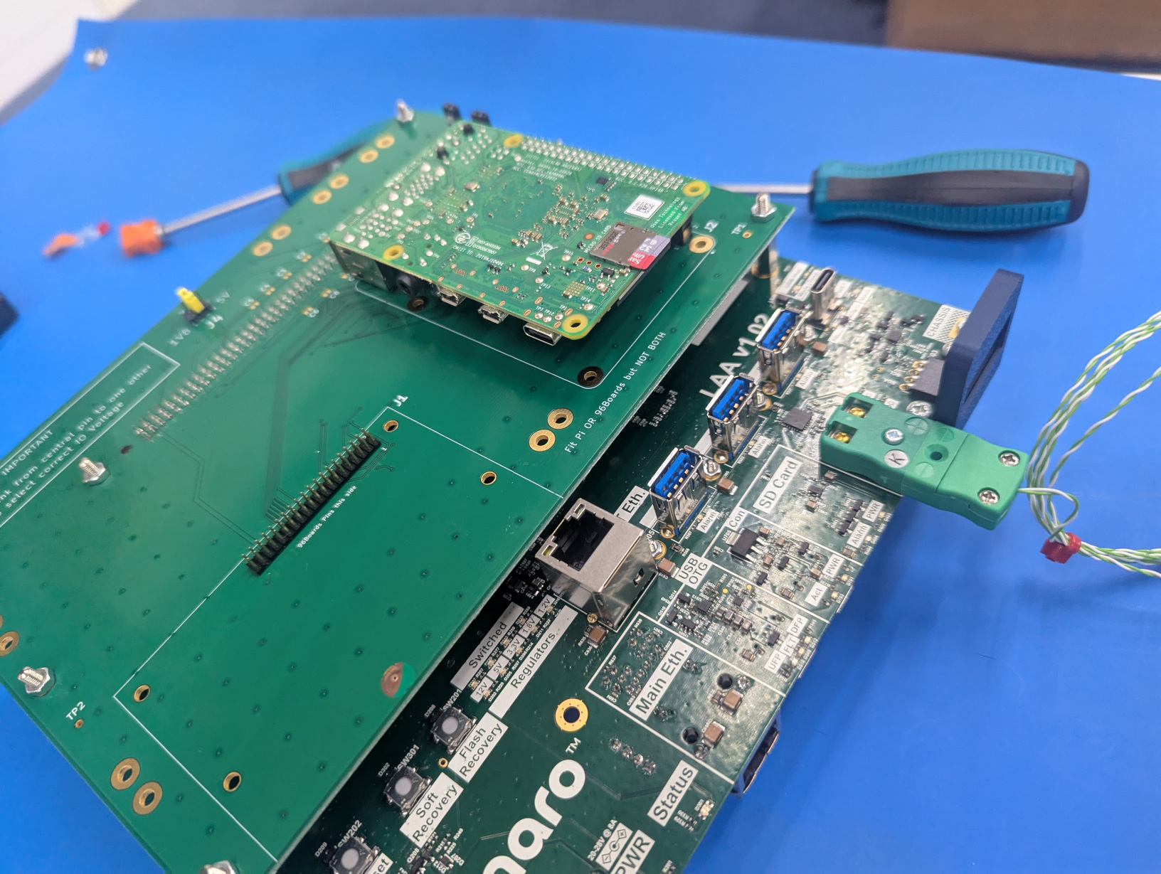
We will now proceed in placing the MIB on the SIB supports, making sure that the big connector in the center connects to the plug on the SIB board.
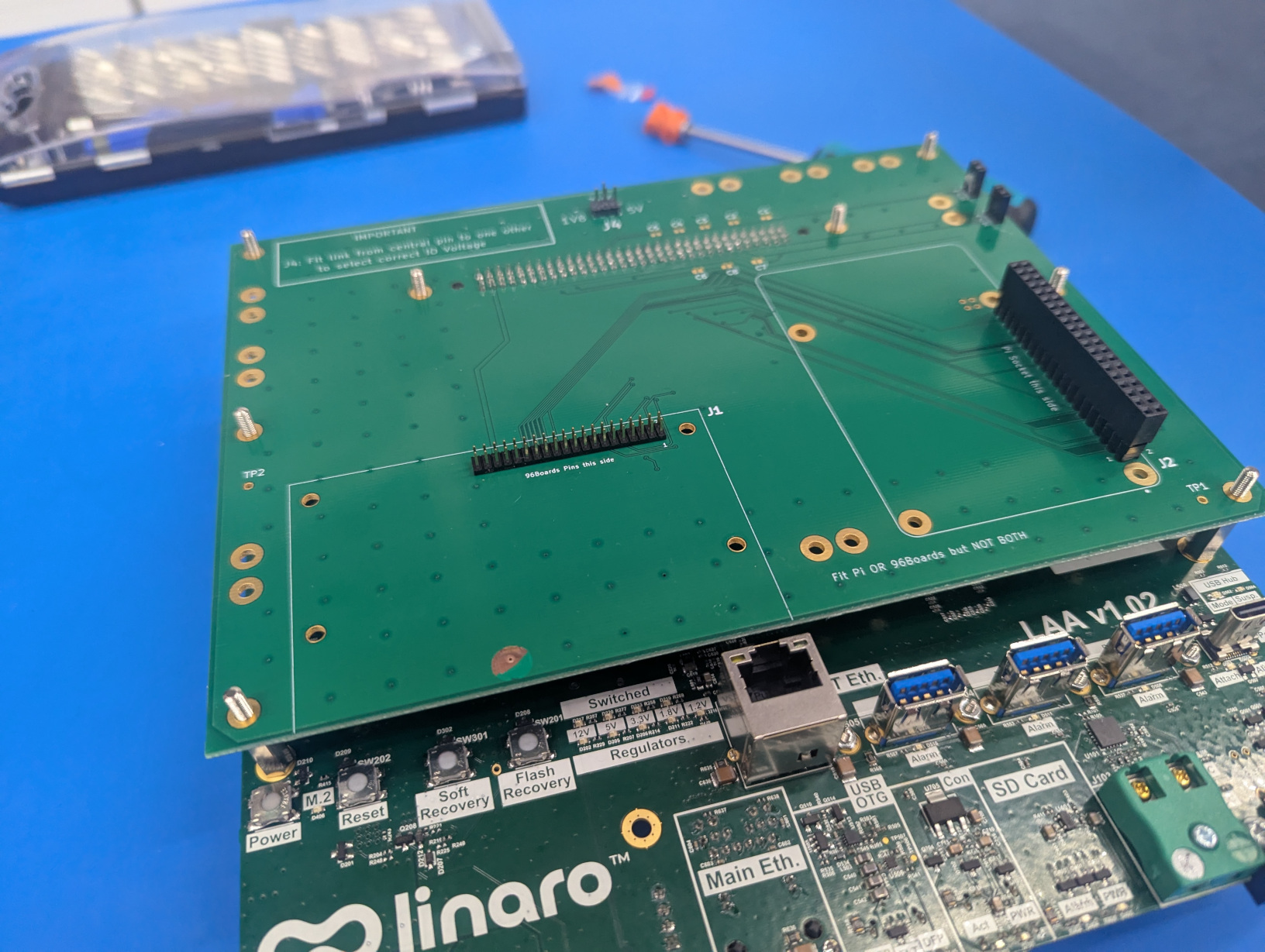
Once we put the hex nuts we should get here.
We can now put the Jumper and set the main voltage to 3.3V.
DUT: RPi 4B
We can now mount the Raspberry PI 4B on the LAA.
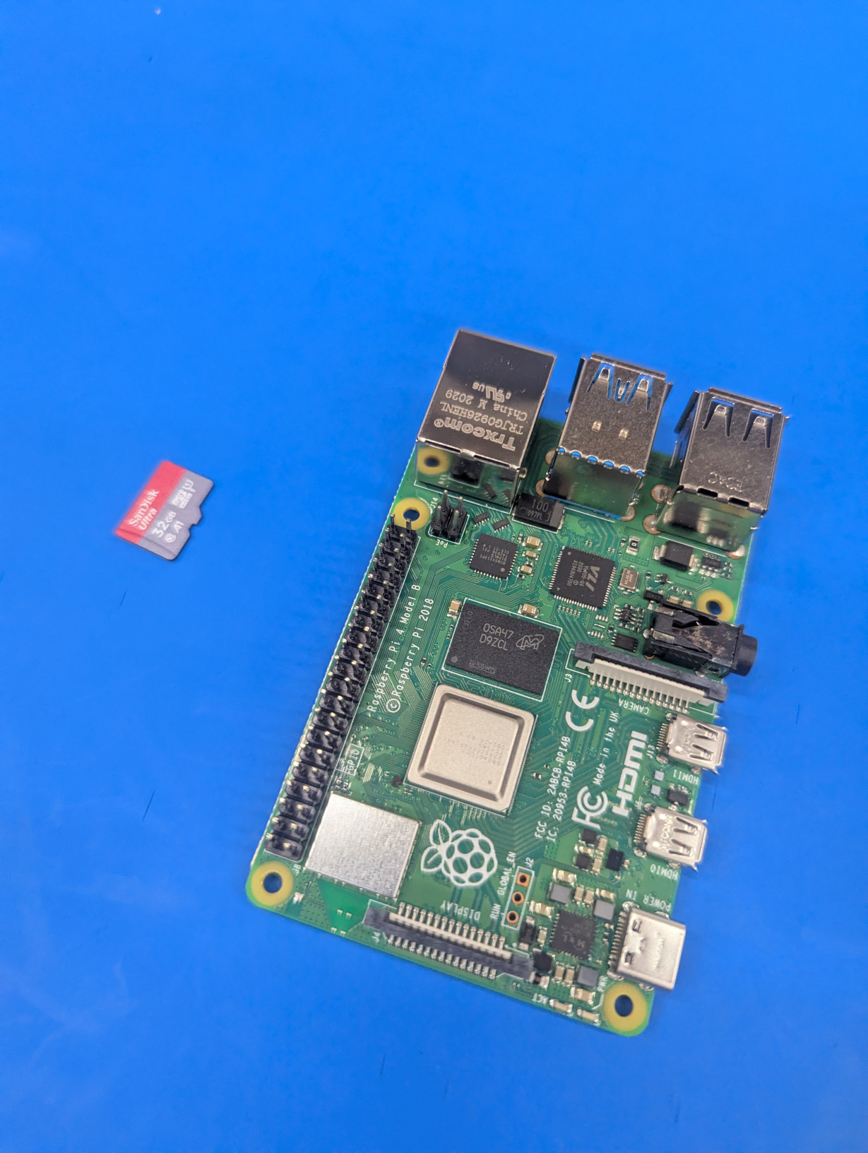
Just pay attention to how you connect it. The Raspberry needs to be placed as indicated on the MIB itself, facing down.
And at this point we want to connect the LAA to the DUT via various cables and connectors. Which cables are required depends on which DUT you have. In our case we are considering a Raspberry PI 4B and you can find all the info on how to connect it here: Raspberry Pi 3B+ and 4B