Phone
This MIB allows you to connect and test a phone like:
Phone MIB 1.0
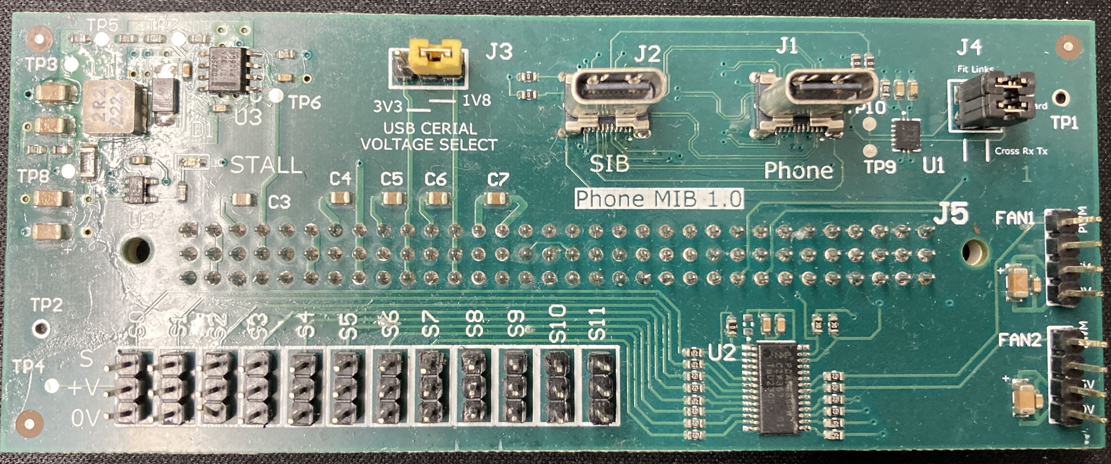
Phone MIB V1.0
Features
Servo driver for button pushing
3d printed jig to hold the device in place
USB Cereal (not working on V1.0)
Can attach fans and heatsinks
Servos
The servos are controlled using the PCA9685 over i2c.
By default it is on i2c bus 3 address 0x40.
A maximum of 12 servos can be attached.
To power on the servos use the following commands:
laam laacli power 5v on
laam laacli power 12v on
The i2c-tools can be used to probe and send commands to the PCA9685:
apt install i2c-tools
i2cdetect
There is also a tool made for the laa phone_mib_ctl that should be available
on the LAA.
phone_mib_ctl --config_file ./mib_config.csv --servos power --action init
The source can be found at phone-mib-ctl.
Phone Jig
The files for 3d printing can be found in phone-mib-jig.
Below follows the original notes provided for assembling the phone Jig.
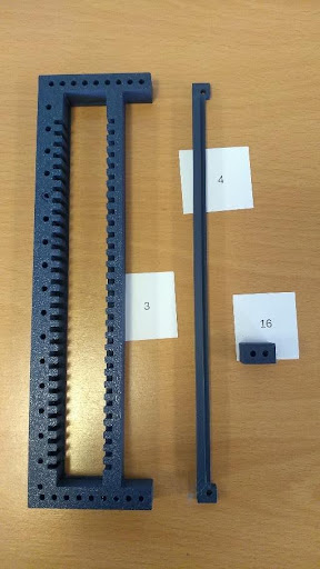
Parts list:
Number |
Colour |
Description |
|---|---|---|
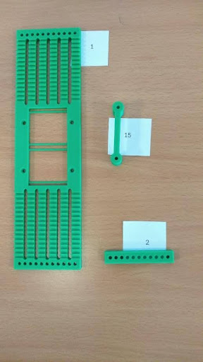
1 |
Green |
Phone carrier |
2 |
Green |
Phone carrier link strap |
3 |
Indigo |
Servo ladder |
4 |
Indigo |
Servo hold down strip |
5a |
Indigo |
Servo hold down arm 15mm |
5b |
Indigo |
Servo hold down arm 25mm |
6 |
Indigo |
Servo ladder combined hold down and spacer |
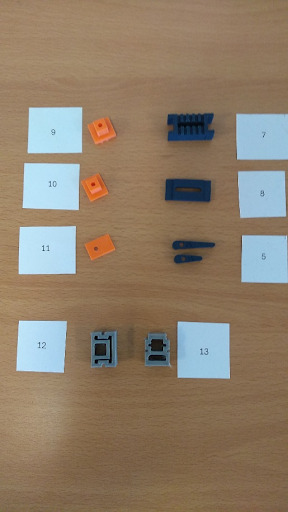
7 |
Indigo |
Phone hold ladder insert |
8 |
Indigo |
Phone hold lock piece |
9 |
Orange |
Phone side hold piece |
10 |
Orange |
Phone end hold piece |
11 |
Orange |
Phone hold cap |
12 |
Grey |
Phone hold flexible buffer type 1 |
13 |
Grey |
Phone hold flexible buffer type 2 |
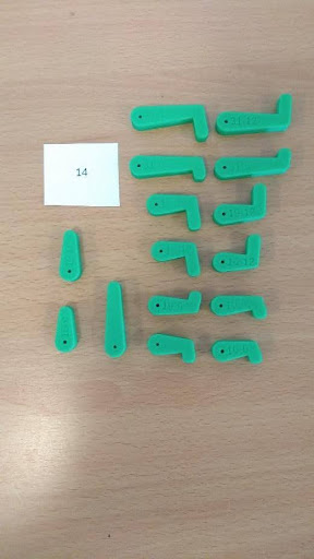
14a |
Yellow |
Servo arms – use with metal servo horn |
14b |
Green |
Servo arms – use with plastic servo horn |
15 |
Green |
Phone Carrier Support |
16 |
Green |
Servo Ladder Spacer |
Notes
The jig is sized for Towerpro MG90D miniature servos.
Servo arms are fixed using M2.5x6 bolts.
Fastening the jig together uses M3 bolts of various lengths: 12,20,25,30,35,40 mm.
We recommend assembling with ordinary nuts first, then replacing with Nylok nuts once positions are finalised
Parts 9 and 10 are very similar, but part 9 is taller. Both can be rotated by 180 degrees to adjust their position by 2mm.
Parts 12 and 13 can be used interchangeably, but have a different degree of compressibility.
Servo arms are marked with the length and offset eg 15-6 for 15mm long and 6mm offset. The smallest of the servo horns which are supplied with the MG90D servo fits into the green arms which are part of this kit. There is also a set of servo arms in yellow which are for use with the metal servo horns.
Assembly
We strongly recommend the following order of assembly.
Use the software to move each servo to a position roughly central in its range of movement before fitting into the jig.
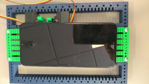
Place the phone carrier [part 1] on two of the Servo ladders [part 3], and use an M3 bolt to pin it in place. There is no need to fasten it at this stage, this is to work out where servos and holding parts are to go.
Place the phone centrally on the carrier without fastening it at this stage.
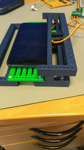
Place servos in the ladder to suit the buttons on the phone. If the phone has buttons on both sides, start with the side with more buttons. Many phones have 3 buttons close together, and it will normally be necessary to add a second servo ladder to accommodate extra servos. There are two methods for doing this, one with the servo ladder above with the arm pointing down, the other with the second servo ladder under the first and using longer servo arms, possibly also with an end offset. Note that the servo ladders can be stacked with a side offset to make adjustments easier.
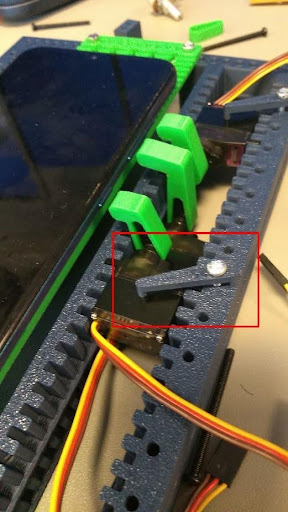
Aligning the Servos
Stacked servo ladder with servo pointing down
Place Phone hold ladder insert pieces where it will be possible to hold the phone securely without getting in the way of the servos. It may be necessary to adjust positions. Note that the servos can be turned round with the use of an offset arm.

Phone hold ladder insert
Move the phone on the carrier so the buttons are close to being vertically above the servo arms.
Fit appropriate servo arms. The horns supplied with the servo are a push fit into the 3D printed arms, screwing the arm into the servo (M2.5 bolt) locks the arm in place.
Use the Phone end hold piece [part 10] and the flexible buffers [parts 12 and 13] to secure the ends of the phone. The flexible buffers are a push fit on the end hold pieces. Note that the flexible parts are not symmetrical. 4mm of adjustment is available by moving to the next ‘step’. 2mm of adjustment is available by rotating the end hold piece 180 degrees and refitting the flexible buffer. Use the Phone hold cap [part 11] to stop the phone lifting. Bolt in place using a suitable length M3 bolt and nut. Do not overtighten.
Fasten the phone carrier to the servo ladder. The phone carrier has holes on 5mm pitch, the ladder has holes on 6mm pitch, so for each 1mm of movement a different hole will come into alignment.
Use the Phone side hold piece [part 9] and the flexible buffers [parts 12 and 13] to secure the phone from moving sideways. 4mm of adjustment is available by moving to the next ‘step’. 2mm of adjustment is available by rotating the side hold piece 180 degrees and refitting the flexible buffer. Use the Phone hold cap [part 11] to stop the phone lifting. Fasten together the Phone hold ladder insert lock pieces [part 8], the Phone hold ladder insert [part 7] the Phone side hold piece [part 9] and the Phone hold cap [part 11] with a long M3 bolt and nut. Repeat for other side hold pieces on the same side
The phone can still move to one side. Repeat the previous step for the other side. Note that there is 4mm of adjustment by using the next ‘step’, 2mm of adjustment by rotating the orange hold piece, and 1mm of adjustment using the position of the phone carrier on the servo ladder.
Prevent servos from moving as follows: If the servo ladders are stacked directly on one another, the lower servos are locked in place by the upper servo ladder. If a second servo ladders is to be mounted above the phone, the servo ladder spacer/hold down [part 6] locks the lower servos in place. Remaining servos can be held down using the hold down strip [part 4] or individual arms [part 5].
Once satisfied, fit the Phone carrier link strap [part 2] for improved rigidity.
Servo hold down arm